4.1 Types of Terminals
4.1.1 Bus Controller
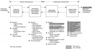
MIL-STD-1553B defines a bus controller as “the terminal assigned the task of initiating information transfers on the data bus.” Notice that the definition does not necessarily depend on the physical design of the terminal but is determined by the assigned task of bus control. This implies that a terminal may have the capability of performing other functions, but during the time when it is assigned the task of bus control it is by definition a bus controller. Figure I-4.1 shows the generalized terminal functional elements that apply to a bus controller.
4.1.2 Bus Monitor
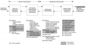
A bus monitor is defined as “the terminal assigned the task of receiving bus traffic and extracting selected information to be used at a later time.” A bus monitor, therefore, is unique in that it performs no transactions on the bus (see figure I-4.2). It not only does not initiate information transfers as a bus controller, it is incapable of any response on the bus, including status response in the monitor mode. In fact, the bus monitor does not require a transmitter so it may be a “receive-only” terminal if it never performs another function (bus controller or remote terminal). However, monitors usually have remote terminal capability to allow the bus controller to check their status health and command new operational modes. Primary applications include collection of data for analysis and back-up bus controller monitoring of system status. The bus monitor, for instrumentation applications, listens to all messages or a subset of messages and stores the data internally or formats and outputs the data to a mass storage device or telemetry equipment. Many monitors are configuration programmable as to their function of message monitoring capability via 1553 messages. In association with a back-up bus controller (whether the back-up controller is either a monitor or a remote terminal), the monitor observes the bus transmissions and collects data, often performing the same operations as the bus controller with the exception of issuing commands on the bus. 8y operating as a monitor, the back-up controller is continuously aware of the state and operational mode of the system and subsystems. Therefore in the necessity of assuming control of the bus, the back-up controller can reduce its start-up time. This type of operation is often referred to as a “hot back-up.”
4.1.3 Remote Terminal
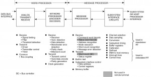
A remote terminal is defined as “all terminals not operating as the bus controller or a bus monitor.” This means that an RT cannot initiate information transfers on the bus as a bus controller and cannot perform the monitor function. It must respond to commands issued by the bus controller in a normal command/response manner. An RT Is identified by a unique address that allows the bus controller to direct specific information to it. Figure I-4.3 shows the generalized terminal functional elements that apply to a remote terminal. Once more it must be emphasized that the definition of an RT is one of function, not form. Any active terminal that is not performing bus control or monitor functions on a given bus at that time by definition is a remote terminal.
It is a common practice that intelligent interfaces provide both bus control and monitor capability as well as RT functions within a terminal. This allows an RT to become a bus controller in the event of failure of the active bus controller.
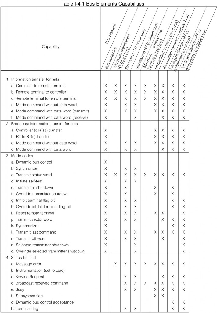
A clear understanding of the functional nature of these 1553 terminals is essential to the understanding of the terminal partitioning. Also, the difference in requirements for each type of terminal will impact their design. Table I-4.1 summarizes a typical set of requirements for several terminal types.
4.2 Functional Elements
4.2.1 Analog Transmitter/Receiver
The analog transmitter/receiver functional element is primarily the analog front end required to interface the terminal’s digital logic with the data bus. This section includes the coupling transformer and fault isolation resistors required for a direct coupled connection to the data bus. The 1553 receiver provides low level noise rejection and a digital output compatible with the digital logic that follows in the decoder. The encoder and transmitter drive the biphase modulated signal to form data word formats defined in MIL-STD-1553B. A timer (analog or digital) is provided to cease transmission after a predetermined time (maximum 800 microseconds). This prevents uncontrolled activity on the data bus. The transmitter/receiver portion is generally implemented using a combination of monolithic chips and/or thick-film hybrids. Today these circuits are widely available in small low cost packages, thus eliminating the need to design your own device.
4.2.2 Encoder/Decoder
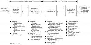
The encoder/decoder (see figure I-4.4) is used to analyze the data bits and words required for data transfer on the receiver side of the terminal. The squared up signal from the receiver is input to the decoder, which senses bit timing to decode the sync pattern, data bits, and parity to identify command/status or data words. Bit patterns other than the sync pattern are checked to verofu proper Manchester encoding. The number of bits per word and parity are verified to complete the bit and word analysis. Error conditions are flagged if any portion of a bit or word is unsatisfactory. The encoder or data transmitter section contains the digital logic to establish both command, status, and data words for formatting, including sync, data, and parity generation. Control signals are provided to the analog transmitter/receiver section to indicate appropriate actions. In state of the art terminals, the encoder/decoder is implemented in a single monolithic, along with the protocol state machine and subsystem interface logic. Usually these integrated chips offer the best way to meet this design function.
4.2.3 Protocol Sequencer and Subsystem Interface
The encoder/decoder is transparent to data word type and contents. Therefore, it passes the words with the error indications to the message processor for further analysis. The message processor continues the analysis by performing command word decoding, address validation, data flow direction (transmission or reception), data reception, message length validation, and data storage when receiving data. and data transmission for transmitting data.
A major task of the protocol sequencer is the subsystem interface control. The subsystem interface complexity may vary from a single parallel or serial handshake for communication to a DMA or shared RAM interface to buffer RAM and/or mail memory.
Also, for standalone remote terminals, which must interface to simple subsystems, the subsystem interface may control and interface with a wide variety of signal conditioners (A/D converter, D/A converters, input and output discretes, serial and parallel channels) either directly or through a controller. For example, the STIC (BUS-65153) provides an 8/16-bit parallel bus for interfacing to a wide variety of simple subsystems. Most of these systems do not contain a microprocessor. Moreover, the ACE series RT-only (BU-65179, BU-65178, BU-65170) and BC/RT/MT (BU-61688, BU-61689, BU-61588, BU-61580) terminals may be interfaced to a host processor and RAM through a variety of configurations: 8-bit and 16-bit internal shared RAM, 16-bit shared RAM (transparent configuration), DMA, and dual port RAM. In addition, the ACE series terminals have built-in architectural features to off-load the operation of the host CPU, control and monitor message timing, ensure data consistency, and facilitate bulk data transfers. The ACE terminals include a number of features to support both polling-driven and interrupt-driven software methodologies.
4.2.3.1 Protocol Sequencer with Remote Terminal Capability
To initialize a remote terminal requires a mechanism for establishing its unique address. Two ways are available; establishing the address using an external strapping of pins to “open circuits” or “ground circuits” to establish a five bit address or host (subsystem or processor) software loaded. Each method has its place. For intelligent subsystems with a capability to change the software and for processors with software loads, software initialization of the terminal address is the most appropriate. External pin addressing in software systems is required to identify acceptable software load and the remote terminal address used for loading the device if the load is supplied via the 1553 bus. For sensors or subsystems with fixed (unchanging) programs and for standalone RTs the aircraft wiring can supply the terminal’s unique address. Notice 2 requires that remote terminals must be capable of being assigned a unique address (address 11111 is still reserved for broadcast for those systems implementing this function) and that all addresses be established via an external connector to the remote terminal. The notice also specifies that changing the address must not require a physical modification or manipulation of any part of the remote terminal (i.e., changing of a memory device containing the terminal’s address). No single point failure in the address strapping should cause a terminal to validate a false address. This means that, as a minimum, the remote terminal should include a parity bit along with the five address lines and should perform a parity check on the programmed address. Notice 2 requires that an RT detect all single failures of the RT address inputs. As a minimum, that address should be validated during power-on initialization.
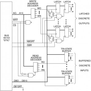
Figure I-4.5 illustrates an interface between a Remote Terminal (RT), (BUS-65153) and a minimum complexity system. That is, a system that does not include a microprocessor. Such systems typically include A/D and D/A converters, switch closures, and simple displays. The STIC incorporates an 8/16-bit DMA parallel data interface, plus a 12-bit address bus. As shown, the STIC may be interfaced to these types of systems with a bare minimum of “glue” logic. Implementing an interface between a 1553 bus and a simple system without the use of a CPU eliminates not only the cost of the processor, but of ROM, RAM, other logic, and software development. For military programs, the latter can be considerable.
Most current subsystems incorporate one or more microprocessors. These range from low-end microcontrollers, used for self-test and simple control functions, to 32-bit processors such as 68040s and 1960s. In either case, an RT with RAM and other support functions, such as the ACE (BU-65170), is generally the preferred solution. The support functions typically include software programmable command illegalization, memory management, message logging, interrupt logic, RT BIT Word implementation, and processor/memory interface. The ACE RT provides all of these functions. In addition, MIL-STD-1553B Notice 2 requires that an RT provide a mechanism for distinguishing between non-broadcast and broadcast messages. With the BU-65170, this includes the capability for storing data words received from broadcast messages in a separate area from non-broadcast data words.
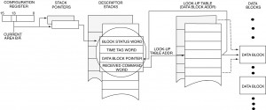
Figure I-4.6 illustrates three methods of RT memory management provided by the ACE. That is, it shows different methods for storing data words for individual RT subaddresses. In each case, there
is a lookup table pointer used to locate the start of a message data block in RAM. The lookup table pointer is initialized by the host CPU. For each mode, note that a 4-word descriptor stack stores information regarding bus channel, message completion and validity status, error conditions, time tagging information, the actual Command Word, and a copy of the pointer that was read from the lookup table. In the single message mode (Fig. 1-4.6 [a]), the same block of data words is overwritten for receive messages, or overread for transmit messages for a given subaddress.
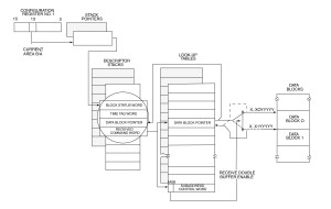
For received messages, the use of subaddress double buffering (Fig. I-4.6 [b]) serves to ensure data consistency by allowing easy CPU access to the last, valid, received data block for a given subaddress. For bulk data transfers such as program downloading the use of the circular buffered mode (Fig. I-4.6[c]) off-loads the host processor by having the RT, rather than the CPU, update the value of the lookup table pointer after valid messages. The purpose of the double buffer and circular buffer features is to off-load the operation of the host processor.
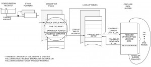
For example, the use of circular buffers eliminates the need for the host CPU to be concerned with individual messages, message errors, or retried messages. To receive a bulk data transfer, it is only necessary for the host to wait for an interrupt request (for circular buffer rollover) and then read the multimessage block of received data words.
4.2.3.2 Protocol Sequencer with BUS Controller Capability
In addition to the capabilities identified above for the remote terminals, bus controller functioning word processors must contain the capability to develop and transmit command words and analyze status words. The same interface control and handshaking is necessary with the bus controller that was needed for the RT. However, since the bus controller can take on many different levels of complexity and the partitioning between hardware and software is not as clear, a general discussion is provided in section 5 on this subject.
4.2.4 Bus Coupler Design
Bus coupler networks, separate from the terminals, are required by 1553B when connected to the data bus via “long stubs.” A long stub is defined to be greater than 1 ft. Direct coupling, which can be implemented without a separate coupler box, is defined for short-stub connections of 1 ft or less (Note: Notice 2 requires that for Navy applications, terminals must have both transformer and direct coupled stub connections externally available, such that either may be used; and that for Air Force and Army applications, ONLY transformer coupled stub connections will be used.) The long-stub coupler network incorporates isolation resistors and a coupling transformer. The isolation resistors are located in the terminal for the direct-coupled case, thus eliminating the need for a separate coupler box if a reliable shielded splice can be made. In most cases, the bus connections can be spliced in the terminal connector.
The coupler-transformer characteristics are very important to the signal integrity and noise performance of the data bus system. The purposes of the coupler are to; (1) provide isolation of the main bus for fault conditions on the stub or in the terminal, (2) provide reduced bus signal distortion effect by increasing effective stub Impedance, and (3) provide termination of the stub when transmitting from the terminal. The isolation resistors and the transformer turns ratio provide the benefits listed above. The terminal input and output specifications for the transformer coupled and direct-coupled connections are separated in 1553B, because of the effects on signal levels and impedance caused by the transformer turns/ratio.
The use of transformers as a means of coupling baseband signals in a balanced transmission line system has proved to be an extremely effective approach. When designed and used properly, transformers can perform effectively to maintain isolation and achieve signal integrity at a relatively low cost and with high reliability. They are not extremely lossy and can readily achieve high common mode rejection.
Coupling transformers are presently commercially available from several sources thus freeing the designer from this design task. Usually the manufacturer of the transceiver will recommend a transformer for use with the device. One point not to be overlooked is temperature rating. Most transformers have a lower maximum operating temperature than the other associated circuit components.
A review of transformer design considerations is given in Chapter 4 of the “MIL-HDBK-1553 Multiplex Applications Handbook.”
