Q. The question that follows assumes that an RT on a dual redundant 1553B data bus has failed to permanent transmit (Babble) on bus A; that the RT fail safe is not operational (due to failure or malicious software); and that the RT is non responsive to the BC 'transmitter shutdown' mode code message on bus B; finally, that the RT is not transmitting Babble on bus B, but continues to Babble on bus A. As the specification (as I understand it) only permits operation on one channel/bus at a time, if the BC and all RTs moved to bus B, would the continued babble on bus A cause any issue to the bus operation? Alternately, can unwanted/authorised transmissions on a 'non-active' bus channel cause the BC/bus traffic to fail due to a conflict over the specification requirement to have only one channel/bus active?
Question submitted December 11, 2019
A.
In theory, if RT is babbling on channel A and cannot be disabled, moving to channel B would be the solution. Channel A babbling would not cause any issue on Channel B. If the RT only has one encoder for both channel A and B, and the encoder has the fault, then if channel A fails, so would channel B.
Answered December 11, 2019.
Q. Can two RTs communicate even though the BC is not available? eg. Initially a BC to RT and RT-RT communication was there between the systems. In case a BC equipment failed and RTs are still live, can they communicate in between (RT-RT)?
A.
No, the BC must initiate all communication.
Q. Can two RTs can be configured on the same channel?
A.
Yes, on one device you can configure two RTs, each of which has its own RT address.
Q. Can we have two RT units with the same RT address, providing that only one of the RT will be powered at a given time?
A.
Yes, you can have two units with the same RT address provided one is powered off. The standard states that all RTs on the bus must have unique RT addresses. So, these RTs must never be on the bus at the same time.
Q. If we broadcast a mode code for self-test to the RTs, and then during the self-test an error is found, would the RT then transmit some kind of message to indicate the error? I am asking this because I read somewhere that RT's don't respond to broadcast messages.
A.
When a remote terminal receives a broadcast command it must never respond. The Bus Controller will get an updated status from the remote terminal when it sends its next non-broadcast command, this is when the BC will be flagged if an error occurred.
Q. I have never found a good explanation of the RT address parity bit. Does it behave the same way on all 1553 systems or can a vendor decide if their system uses even or odd parity on RT address strapping?
A.
For all 1553 systems RT Parity bit shall be used to set odd parity for the RT address.
Q: How does RT behave on receiving an error in sync bit?
Question submitted March 11, 2019
A.
If the RT receives an error in the sync field of the Command word, the command word should be ignored. If the RT receives a Sync error in the data word, the data word should be ignored and the message error bit must be set in the status word.
Answered March 13, 2019.
Q: How does an RT which had become BC, again become RT and what does the previous BC do once it gives control to an RT to become BC? What will happen if we have only 1BC and 1RT and BC gives RT command to become a BC?
Question submitted February 27, 2019
A.
In a 1553 system where there are RTs and a BC, the BC can request an RT to become an BC. For this to happen the following steps are needed:
Current BC sends mode code 0 (Dynamic Bus control) to an RT.
The RT would respond to request by setting the Dynamic Bus Control bit in the Status word.
The former BC will then configure itself as an RT or go offline.
The former RT will configure itself as a BC
New BC starts to send out commands.
The only way for the previous BC to switch from RT to BC is to again follow the same steps listed above.
Answered February 27, 2019.
Q: Try to interpretate MIL-STD-1553B error message: Status word RT address incorrect.
Question submitted November 8, 2017
A.
If RT address in status is incorrect, the RT responding is doing so when not addressed.
Answered March 27, 2018.
Q: 1. How does a 1553 receiver determine the difference between no data being received versus a logic 1 or logic 0 being received? This is needed to determine gap times between words etc?
2. How does a 1553 receiver determine the difference between a status word and a command word since the SYNC patterns are identical?
Question submitted November 1, 2017
A.
1. We look for the zero crossings in the message. The zero-crossings set up the timing to decode the message. All logic 1 or 0 have no zero-crossings.
2. Status word only happen in response to a command and come from the RT. An RT never sends a command. But in monitor mode Status need to be within a certain gap time, if the internal gap timer has expired the monitor would expect a command word.
Answered November 1, 2017.
MIL-STD-1553: BC (Bus Controller)
Q. In an RT-RT transfer, do the receive word count and transmit word count have to be the same? Is it permissible to have the receiving unit setup to receive the first 27 words of a 30 word transmit, so the BC can capture all 30 words in the same transmit? (Receiving RT is not able to receive all 30 words.)
A.
Yes, the receive word count must be equal to the transmit word count or you will get a decoder error because the receiver would see a high word count when the message is longer than what is expected.
Q. How does the BCC take control of a defected BC bus?
A.
The BCC can always switch channels if the other bus is defective.
Q. I am working on a system in an aircraft, and its RT is receiving both channel A & B failures intermittently?
A.
You need to make sure the bus is terminated correctly.
Q: While sending a Transmit command,how is parity bit set? We use odd parity but how do we set it initially without knowing the data?
Question submitted March 11, 2019
A.
The parity bit is always set by the transmitting terminal. The transmitting terminal should have a parity generator that affixes a parity bit after the transmitted 16 bits of data are shifted out on the 1553 bus.
Answered March 13, 2019.
Q: What are the different types of blocks required to construct a 1553 bus controller?
Question submitted July 4, 2018
A.
The blocks need to for a Bus Controller are: IP/ASIC that instantiates BC protocol per Mil-Std-1553, Memory for messages and responses, 1553 transceiver and transformers. Various vendor sell this configuration as a packaged part.
Answered July 9, 2018.
Q:What is the relation between message scheduling rate and minor frame in 1553B?
Question submitted January 23, 2018
A.
A minor frame is a subset of a major frame. The major frame has its own schedule. Multiple minor frames of the same command can be in the major frame. If the Major frame is 1 second and a minor frame repeats in a major frame every 10 ms, the rep rate would be 100 Hz.
Answered January 29, 2018.
MIL-STD-1553: Validation
Q. We are developing a MIL-STD-1553 remote terminal application and would like to ask an expert if a validation test plan and production test plan are mandated by the mil standard to demonstrate compliance to the MIL standard 1553, or are those suggested test plans and can be looked at as examples for customized test plans?
A.
The validation test plan and production test plans are not mandated by Mil-STD-1553. They are requirements invoked by customers. The validation test plan is to make sure the designer did not miss designing in any of the MIL-STD-1553 requirements. Passing the test at room temperature does not mean the part meets all the design specs. The design must function as an RT over all the environmental requirements.
Q: With respect to RT VALIDATION TEST PLAN, 5.2.1.2.1, Pair 8 H (GAP) A, if the BC has a timeout set to 22us and an intermessage gap set to 4us What would be the time from H's parity zero crossing to A's sync data crossing? 22 or 4 us?
Question submitted August 21, 2018
A.
Because the BC is sending a Broadcast command, it is not waiting for a response. Therefore the gap time is 4 us.
Answered August 21, 2018.
Q: 5.3 Noise Rejection Test fig 9A, what R1,2,3,4 and R5 are use for?
Question submitted March 26, 2018
A.
Resistors R1, R2, R3 R4 and R5 are used to mimic the 1553 bus load.
Answered March 27, 2018.
MIL-STD-1553: Applications
Q. When testing 1553 interface cards, is it a requirement to have two separate units, one as the UUT and the other as its partner vs having one card, or multiple cards in one system cabled up to itself, and transmitting data on one channel, and receiving on another channel?
Question submitted November 24, 2020
A.
Single device, multi-channel testing is commonly done. A single device with multiple channels can be connected so that the channels communicate with each other. As long as those channels are hooked up to a properly terminated transformer bus coupler, then you will be able to send and receive data between each channel with no issues. Same goes for multiple cards in a single system. It is an easier picture to paint when you have two separate devices, but one device will work just fine.
Answered November 24, 2020.
Q. I want information on 1553B card connectivity. I have a laptop without a PCMCIA slot but I still want to use this card. Please suggest a suitable external USB based converter to use.
Question submitted January 7, 2020
A.
Any converter will work.
Answered January 14, 2020.
Q. I was looking at developing an application to take some information from the 1553B databus via an Aircraft Interface Device. Do I need information from the Aircraft manufacturer on how to access the data I want, or is this a standard? (e.g. position information)
Question submitted October 24, 2019
A.
The aircraft information on position or other functions are standardized per aircraft platform and are not published. There is some information published in MIL-STD-1760 on what each sub-address means in the system for stores.
Answered October 25, 2019.
Q. How can you test a 1553B to see if it is working correctly?
A.
To validate that 1553B you need to pass the MIL-STD-1553 Validation Test Plan. There is a test plan for a BC and one for an RT. To run the test plan you need a MIL-STD-1553 simulator board that plugs into a PC and you need validation software. Both are available from a number of vendors. The simulator output gets connected to a bus coupler and then to the 1553 device you want to validate.
Q. Does both channels A & B share the same common shield in a bus?
A.
There is a shield for channel A and a shield for channel B.
Q: Is there a MIL-Handbook that elaborates on the scope and test steps for bus controller protocol test?
Question submitted April 3, 2019
A.
AS4113 elaborates on the scope and test steps for bus controller protocol test.
Answered April 3, 2019.
Q: Kindly suggest me the online resources to read about MIL Std 1553B protocol in detail. I am currently studying from MIL Std 1553 Designer's guide by DDC.
Q: Can we use only broadcast option for communication between BC and three identical LRUs?
Question submitted March 2, 2018
A.
Yes, you can send broadcast messages to these thru LRUs, but must address individually for transmit commands.
Answered March 27, 2018.
Q: Is there a timing requirement in the specification that defines the maximum timing for a controller to change from RT to BC or BM to BC?
Question submitted February 27, 2019
A.
There is no specific timing for the change over in the 1553 spec. This is a system level requirement and timing should be set to keep up with the requirements for transaction to each RT.
Answered February 27, 2019.
Q: Is there a mil std spec for BGA ball pull strength?
Question submitted August 31, 2018
A.
What you are referencing is ball shear strength, and it is specified by JEDEC standard JESD22-B117A.
Answered September 4, 2018.
Q: I am curious if anyone has knowledge regarding the 1553 architecture on early model (Block 10) F-16 aircraft. Our company is planning to perform a bus capture on foreign owned block 10 F-16s and we are not sure what connectors might be used on the aircraft (did they use traditional twinax connectors? Guessing no since it was way early in the life of 1553. Is everything direct coupled as opposed to transformer coupled? Thanks for any insight you may have.
Question submitted August 7, 2018
A.
Sorry we do not know if the Block 10 used Twinax, but we do know its transformer coupled.
Answered August 14, 2018.
Q: If we have to do any change or up-gradation in MIL-STD-1553B, which is the agency or organization we need to approach?
Question submitted July 26, 2018
A.
To upgrade Mil-STD-1553 you must contact SAE (Society of Automotive Engineers).
Answered July 26, 2018.
MIL-STD-1553: Layout
Q: Should 1553 differential signals be routed as differential pairs?
Question submitted June 25, 2018
A.
The 1553 differential signal do not have to be routed as differential pairs. Just make sure the trace length match.
Make sure to avoid routing other signals adjacent or parallel to these signals.
Answered June 25, 2018.
MIL-STD-1553: Miscellaneous
Q. We want to implement 1553B IP core in FPGA. For this we are trying to purchase the complete 1553B specification documents. From where can it be purchased?
A.
The MIL-STD-1553 standard can be found on www.SAE.org.
Q: I need the price of the full collection of MIL standards and history.
Question submitted July 4, 2018
A.
This site does not provide for the sale of Military standards.
Answered July 9, 2018.
Q: A client asked me the difference between MIL BUS Protocol Specification v7 and v9. Can you tell me what the changes are?
Question submitted July 4, 2018
A.
Mil-std-1553 is revised by notices. It is currently at Notice IV.
What standard are you referring to for version 7 and 9?
Answered July 9, 2018.
Q: I believe Direct and xmfr coupled devices can live on the same 1553 bus, what special things should I watch out for when this occurs?
Question submitted November 27, 2017
A.
There are no issues when using both direct and transformer coupled on the bus.
Answered March 27, 2018.
Q: If you are in Selective Monitor Mode only on the bus do you have an address? Does the Bus Controller have anyway of knowing you are on the bus?
Question submitted October 31, 2017
A.
Monitors do not get addresses. Addresses are reserved for RTs.
The BC will never know that a Monitor is on the Bus. There is no mechanism for determining the Monitor is on the BUS.
Answered November 1, 2017.
Q:We are working on a structure to test avionics sensors which may require a longer than normal 1553B data bust to retrieve sensor data. What is the longest data cable that can be supported under these conditions? The structure may require more than 300 ft. in length.
Question submitted August 16, 2017
A.
There is no length requirement for 1553B, therefore a bus greater than 300 ft could be possibly.
Answered August 17, 2017.
Q:I wonder whether synchronize command may disturb the normal work of RTs on the bus, and whether one can synchronize only two RTs only (same sync for only 2 RTs, not the whole bus)?
Question submitted July 20, 2017
A.
The synchronize command will not disturb the normal work of the RT’s on the bus.
Also, the is no way to synchronize 2 RT only. To synchronize all RT use the broadcast command. You can synchronize one RT followed by the other to get closely synchronized timers. How close depends on your system.
Answered July 28, 2017.
Q: Is it possible to certify the MIL-BUS-1553 per civil requirements? (DO-178/254)
Question submitted July 20, 2017
A.
You can certify the design of the 1553 design components (ASICs, FPGAs, Memory) per DO-254. This includes the VHDL/Verlog code for the ASIC and FPGA. Certifying to DO-254 is a costly and time consuming process and is best done on new design efforts.
As for DO-178, the Host software can also be certified.
Answered July 20, 2017.
Q: we are using dual 3.3V pulse transformer (DLVB4233) along with BU-64743G8-240 Mini ACE terminal . Is it required to use additional TVS (Transient Voltage Suppressor) diodes against lightning protection as per RTCA/DO160D on MIL-BUS ? Are this transformer is capable to with stand. Please clarify.
Question submitted June 12, 2017
A.
There is no need to add a TVS or lighting protection to the 1553 Bus. All protection is handled by the transformer.
The reason for the transformer is to isolate the terminal from faults.
Answered June 19, 2017.
Q: Is there any 1553 connectors that has TVS or lightning protection built in?
Question submitted May 10, 2017
A.
There are no BNC connectors with protection. For 1553 no lightning protection is needed due to the standard calling out the use of transformers.
The transformer are used for protection of the terminals.
Answered June 19, 2017.
Q:I'm trying to understand what 1553 is. I am not an engineer. The gist of it seems to be its a way for avionics equipment to communicate electronically by speaking a common language. Is that close? What need did this standard fulfill? What would be the world be without it?
Question submitted April 9, 2017
A.
MIL-STD-1553 was created to make wiring aircraft less complicated. Before hand you had point to point wiring which increased complexity, weight and cost to aircraft. With MIL-STD-1553 and its bus topology you have a cost/complexity/weight savings along with a reliable protocol.
Answered June 19, 2017.
Q: What are the three mode of 1553?
Question submitted May 31, 2017
A.
The three modes are Remote Terminal, Monitor, Bus Controller.
Answered May 31, 2017.
Q: kindly tell the steps of configuring the 1553 standard as BC.
Question submitted February 28, 2017
A.
The 1553 standards describe the functions of BC/RT/MT. It does not tell how to configure for a BC. Some device manufacturers have devices that can be configured as a BC or RT or MT. Please review their datasheet for proper configuration of BC
Answered March 3, 2017.
Q: What will be the effect of reversing polarity of bus wiring from one end of a bus cable jumper to the other? Such as cable from RT to bus coupler stub in a transformer coupled bus - blue to center and white to ring at one end, and white to center and blue to ring at the other end.
Question submitted February 13, 2017
A.
Connecting “blue to center and white to ring at one end, and white to center and blue to ring at the other end” won’t work.
Answered March 3, 2017.
Q: Could you please provide me a rational that explain why, on the bus 1553, any failures on the interfaces of the Bus Controller doesn't damage the electric/electronic components on the interface of Remote Terminal and vice versa?
Question submitted February 1, 2017
A.
Damage doesn’t occur because the devices (RT and BC) are isolated by transformers when transformer coupled. Direct coupling to the bus provides no isolation, but the isolation resistors, which are also used with transformer couple mode, provide short circuit protection. The value of these resistors will current limit the leg of the transmitter which is being shorted. If a BC has an interface problem there is also the protection of switching to the alternate BUS. Also, if the BC see an interface issue with the RT, it switched to the alternate bus. If a BC or RT is babbling, and preventing the BUS to be used by other RTs, there is a watchdog timer in each device that will stop the babbling and flag the error so the alternate bus can be used. If the RT or BC interfaces becomes shorted the isolation transformer and resistors will prevent the bus from loading down. If the short is on the BC side, the BC will switch the bus it uses to communicate will all the RTs. If the RT interface is shorted the BC will just switch to the alternate bus when communicating with the faulty RT .
Answered March 3, 2017.
Q: As we know, the MIL-STD-1553B has the lightning immunity,but I could not find the details about it.If the DO-160G standard is used, which lightning protection levels can be achieved. Does we have any Accurate data in the A350 XWB project.
Question submitted December 23, 2016
A.
Lightning Protection Level is vendor/device specific. The MIL-STD does not call out a spec on lightning protection. Most MIL-STD-1553 implementations do not require or use external lightning protection. This is because most 1553 isolation transformers provide high levels of commmon mode rejection and dielectric withstand, thereby obviating the need for external protection. MIL-STD-1553 terminals provide immunity to common mode voltages of 1600V and higher.
Answered March 3, 2017.
Q: I need complete mil-std 1553 bus spacification what they will use.
Question submitted December 13, 2016
A.
Copies of the Mil-Std-1553 standard can be found on most 1553 vendors web site and can be used for design purposes. For example, Section II of Data Device Corporation’s (DDC) MIL-STD-1553 Designer’s Guide includes the MIL-STD-1553B standard document.
Answered March 3, 2017.
Q: Two avionics systems are to be interfaced through 1553B bus. One will act as Bus Controller and another as Remote Terminal. The distance between these two systems is 300mts. Can 1553B bus work for this much distance with bus couplers? And also please advice what is the maximum distance 1553B bus can support?
Question submitted December 9, 2016
A.
MIL-STD-1553 does not specify a maximum bus length. Instead, the design of the bus cable, couplers, stubs, and terminals must provide a range of bus voltages between 1.4 and 20 volts peak-to-peak to all direct coupled stubs; and a range of voltages between 1.0 and 14 volts peak-to-peak to all transformer coupled stubs.
As explained below, maximum bus length is mostly a function of cable attenuation (which is based mostly on cable resistance), and the number of stubs and stub lengths. Signal rise and fall times are secondary factors, since transmission over longer distances tends to filter the 1553 signals such that they more closely resemble 1 MHz and 500 kHz sine waves, rather than trapezoidal waves.
According to paragraph 4.5.1.3 of MIL-STD-1553B, the maximum cable loss (attenuation) is 1.5 dB/100 feet at 1 MHz. To enable longer length buses, cables with lower attenuation should be used.
To compute the voltage at various points along a MIL-STD-1553 bus, it’s necessary to consider both bus attenuation and the effect of stubs.
The impedance looking into a transformer coupled stub including the coupling transformer is shown in Figure 1. This impedance, which is generally computed at 1 MHz, is a complex number.
Figure 1. 1553 Stub Impedance
The equation for this impedance is:
; where
Z0 = cable characteristic impedance, which must be 70 to 85 ohms (nominally 78Ω)
ZXF = coupling transformer input impedance at 1 MHz, looking from the main bus towards the stub. ZXF must ≥ 3,000 ohms.
; where
ZL = load (terminal) impedance, which has a minimum value of 1,000 ohms
, where
l = stub length, in meters;
, where
k = 0.6
c = 3.0•109 m/sec
f = 106 Hz
There will be voltage attenuation for each length of bus cable and at each stub. Referring to Figure 2, the equation for cable voltage attenuation over a length L of cable (in feet) is:
, where
VIN = voltage going into bus cable of length L;
L = length of bus cable, in feet
A = cable attenuation, in dB/100 feet (maximum A = 1.5)
VOUT = voltage after L feet of cable
Figure 2. Cable Attenuation
Referring to Figure 3, the impedance looking from the bus into a stub (before the stub) is:
Figure 3. Bus Impedances and Voltages Near Stub Connection
ZBUS_AFTER_STUB in Figure 3 is a function of the cable impedance, the distance to the next stub, and the bus impedance just before the next stub, ZBUS_BEFORE_NEXT_STUB. ZBUS_AFTER_STUB is computed as follows:
, where
, L = distance to next stub, in meters (not in feet);
, k = 0.6, c = 3.0•109 m/sec, and f = 106 Hz.
For the case of the last length of bus prior to the terminator, Z_(BUS_AFTER_STUB)= Z_0.
Assuming a voltage wave propagating from left to right in Figure 3, the bus voltage just after a stub connection is computed by:
These calculations repeat back until the transmitting BC or RT terminal. Referring to Figure 4, the bus impedance presented to the transmitting BC or RT is:
The output voltage driving the terminal’s stub will be about 20 volts peak-to-peak. Therefore, the voltage on the bus side of the coupling transformer will be about 28 volts peak-to-peak. Assuming a voltage source transmitter, the voltage across the bus will be:
, where VBUS-TX = the voltage transmitted by the BC or RT. This allows the bus voltage to be computed at any point along the bus. If the voltages presented to all stubs on the bus is between 1.4 and 20 volts peak-to-peak for all direct coupled stubs, and between 1.0 and 14 volts peak-to-peak for all transformer coupled stubs, then the design of the bus (stubs, couplers, terminals, etc.) is compliant to MIL-STD-1553B.
Figure 4. Transmitter Voltage and Bus Impedance
Answered March 3, 2017.
Q: Are 1553 packets Big Endian like Ethernet?
Question submitted November 8, 2016
A.
No, little endian if we are talking about bits. Bit 15 is sent first (15, 14, 13, 12, ….2, 1, 0). Bit 15 – 8 is the Most significant Byte, while bits 7-0 are the least significant Byte.
Answered March 3, 2017.
Q: Are there any existing 1553 SPICE models for time domain analysis of a bus?
Question submitted November 3, 2016
A.
Because the bus is a product of the drivers and the magnetics, Spice models are not commercially generated for the 1553 bus. Although SPICE could be (and is) used to model transceiver circuits, this question relates more to creating a time domain model of the bus and stubs; i.e., it would need to model the transmission line effects, which gets into crunching partial differential equations. Air framers – Boeing, Lockheed, NGC, etc. – have proprietary software programs for doing this.
Answered March 3, 2017.
Q:I am trying to determine the windings ratio needed for a coupling transformer that connects a remote terminal to the main bus.
From my research, I have seen either two ratios used: 1:1.41 and 1:1
1) In what situations would each be used?
A second part of the question that may be related:
2) Are remote terminals designed with internal transformers? If so, would we still need a transformer in the coupler at the opposite end of the stub cable?
Question submitted November 3, 2016
A.
1. They both are used for isolation. The turns ratio for the coupling transformer, which connects a stub to a bus, is ALWAYS 1.0:1.4, going from stub to bus, or 1.4:1.0 going from bus to stub. The turns ratio for a terminal’s isolation transformer is variable. This is typically a step-down turns ratio (or possibly 1:1) for a 15V or 12V transceiver, and a step-up turns ration for a 5V or 3.3V transceiver.
2. ALL 1553 terminals include isolation transformers, for either direct-coupled or transformer-coupled connections. The coupling transformer is only required for transformer-coupled terminals.
Answered March 3, 2017.
Q: When routing 1553 on a pcb, should it be routed as a differential pair at 78 ohms?
Question submitted November 2, 2016
A.
Assuming the use of transformer coupling, the best practice is to establish a differential impedance of about 78 ohms for MIL-STD-1553 stub signals on PC boards, including backplanes. This will closely match the characteristic impedance of the 1553 stub cable.
For example, according to this impedance calculator (click on “Microstrip Zdiff”), if the 1553 signal traces are on one of the PC board’s outer layers, 15 mils wide, and 0.7 mils thick, spaced 5.5 mils apart and 10 mils from the closest the closest ground or power supply plane, the differential characteristic impedance Zd is computed to be 78.2 ohms. This calculation assumes that the relative dielectric constant (εr) for FR4 board material is approximately 4.7.
Answered March 3, 2017.
Q: What is the correct terminology to use to call the angle that a Gull-wing Lead makes with the seating plane? Typically it is just a few degrees?
Question submitted October 20, 2016
A.
The Heel.
Answered March 3, 2017.
Q: In the White Paper A Practical Approach to Commercial Aircraft Data Buses section 1.2 there is this phrase: A higher stub impedance will produce a higher ZL and result in a lower reflection coefficient (CR). Below there is the equation of the reflection coefficient. CR=(ZL-Z0)/(ZL+Z0). My comment/question: I think the higher is ZL and the closer to 1 is CR. So the higher is ZL and the more reflections there are (CR=1). What I am missing? Thanks for your help.
Question submitted October 13, 2016
A.
To clarify, “higher stub impedance” in the white paper refers to the stub load impedance (ZL). For high values of ZL (approaching ∞), the reflection coefficient approaches +1. This implies that the reflected signal is essentially the same amplitude as the original signal. Further, if the stub length is short relative to the signal wavelength, the reflected signal will be close to being in-phase with the original signal. Since the maximum recommended MIL-STD-1553 stub length is 20 feet and the wavelength of a 1 MHz signal traveling down twisted/shielded cable is approximately 600 feet, the phase of a reflected 1 MHz signal from a 20-foot stub will be about 24° out of phase from the original signal. Based on this, the reflected signal from a high impedance 1553 transceiver at the end of a short stub will be nearly the same amplitude and phase as the original signal. This minimizes the amount of distortion to the signal traveling down the bus.
Answered October 18, 2016.
Q: Do the A & B busses on the 1553 RT share the same address?
Question submitted October 13, 2016
A.
All dual redundant Remote Terminals (RTs) on a MIL-STD-1553 bus share the same RT address on both their A and B channels.
Answered October 18, 2016.
Q: What is the reason behind the number series in mil std?
Question submitted August 30, 2016
A.
The number ‘1553’ was an arbitrarily number assigned by the US DoD.
Answered October 18, 2016.
Q: DI-MISC-80343 which references MIL-HDBK-1553A Section 80 has been used to document 1553 RTs. What is the current preferred format and/or tailoring to DI-MISC-80343?
Question submitted August 9, 2016
A.
There are multiple standards that provide guidance for the formatting of MIL-STD-1553 messages and ICDs. As you point out, there’s MIL-HDBK-1553A Section 80 and DI-MISC-80343. Another standard that provides guidance in this area is SAE standard is AS15532, “Data Word and Message Formats”. MIL-STD-1760, “Aircraft/Store Electrical Interconnection System”, defines the messages used for weapon systems (bombs, missiles, rockets, launchers, racks, etc.). For specific systems, the decision of which of these (if any) or other standards to use is left to the discretion of the individual system integrator.
Answered October 18, 2016.
Q:Can we do frequency response characterization of a digital channel like MIL-1553B. Basically I want to know whether bode plots will be a valid tool for MIL-1553B channel or not.
Question submitted July 28, 2016
A.
This certainly could be done. That is, a spectrum analyzer could be used to display a frequency domain plot of a 1553 signal. Such a plot would exhibit the fundamental and harmonic components of the 1553 waveforms, where the fundamental frequencies are 250 kHz, 333 kHz, 500 kHz, and 1 MHz. More commonly however, 1553 waveforms are viewed in the time domain, since shows the essential parameters including transmitted and received amplitude, rise/fall times, residual voltage (dynamic offset), overshoot and ringing, transmission line reflections, and noise on the bus.
Answered October 18, 2016.
Q:Is there a minimum length cable restrictions between two Data Terminals or between two stubs. At various places it is mentioned that the Data Terminals and couplers must be at least 01 meter apart. If yes, could you please specify the reason.
Question submitted July 19, 2016
A.
No, MIL-STD-1553 does not include a spec for the minimum distance between stubs on a bus. In fact, there are multi-stub couplers available for which the distance between two stubs on a bus can be on the order of one inch.
Answered October 18, 2016.
Q: I have worked under this standard and have been recently asked about the certificate of it. Please inform me of how to go about acquiring such.
Question submitted July 14, 2016
A.
I’m not aware of certificates specifically. However, there are companies that conduct training courses about MIL-STD-1553. In addition, there are also companies that validate the operation of MIL-STD-1553 bus controllers, remote terminals and monitors.
Answered October 18, 2016.
Q: Can a bus monitor fail to become a bus controller and broadcast onto the bus?
Question submitted July 5, 2016
A.
Unless directed otherwise, bus monitors operate as passive bus monitors. Many terminals function as Remote Terminal (RT) and Monitor simultaneously. RTs and RT/Monitors may be commanded to switch to Bus Controller (BC) mode by receiving a Dynamic bus controller mode code command from the existing bus controller. Alternatively, a monitor or RT/monitor may be programmed to automatically switch to BC mode following a period of time when the Monitor doesn’t detect any messages transmitted over the bus by the current BC. A third method is for a node on the bus operating as an RT and/or monitor to be able to receive an out-of-band (probably discrete) signal indicating that the current BC has failed, thereby requesting it switch over to BC mode. To answer your question, as in any system, yes it is possible for a bus monitor to fail to successfully switch over to bus controller mode.
Answered October 18, 2016.
Q: What is the baud rate of MIL 1553?
Question submitted June 5, 2016
A.
MIL-STD-1553’s nominal data rate is 1 Mb/s. Since the Manchester bi-phase L encoding scheme used by 1553 involves two 500 ns symbols (Manchester half-bits) per data bit, the baud rate for 1553 is 2 Mbaud.
Answered July 11, 2016.
Q: How could i go about decoding the MIL 1553 using Picoscope 6?
Question submitted June 2, 2016
A.
Like any oscilloscope, MIL-STD-1553 waveforms can be viewed using Picoscope 6. For best results, the scope should monitor both legs of a 1553 bus, and should display the differential waveform, rather than two single-ended waveforms. I’m not aware of any software to decode 1553 signals captured by Picoscope 6, however I’d think this would certainly be possible. This would involve decoding the captured waveform to determine Command, Status, and Data sync symbols, along with Manchester encoded half-bits. The half-bit decoding algorithm would need to tolerate errors in zero-cross-to-zero-cross times of up to ±150 ns from their nominal values of 500, 1,000, 1,500, or 2,000 ns.
Each Manchester-encoded data bit would need to be checked for validity (i.e., one half with a positive differential voltage and one half with a negative differential voltage), and its data value decoded from two consecutive half-bits. This is a fairly straightforward process. Further, to correctly decode all words, in addition to checking Manchester encoding, all words would need to be checked for correct sync pattern, correct data bit count (16 plus parity), and correct (odd) parity. Further, all 1553 message segments need to be checked for correct word count, consistent with MIL-STD-1553 for the respective message format.
Answered July 11, 2016.
Q: Can we use mil 38999 series III connector for MIL 1553B communication for a length of 5 meters? which is efficient direct coupling or transformer coupling? can we use splicing instead of stubs?
Question submitted June 6, 2016
A.
Yes, MIL-DTL-38999 connectors are commonly used for 1553 signals. In general, transformer coupling is preferred over direct coupling. The advantages of transformer coupling include that it provides a two-to-one improvement (increase) in the value of the stub impedance presented to the main bus. This increases the bus voltage, while reducing the amplitudes of transmission line reflections on the bus. Transformer coupling also provides improved isolation relative to direct coupling. This improves common mode rejection and therefore lightning immunity for terminals connected to the bus.
As for splicing, direct coupling is essentially a form of splicing off a 1553 bus. However, note that the maximum recommended length of a direct-coupled 1553 stub is one foot. The maximum recommended length for transformer-coupled 1553 stubs is twenty feet.
Answered July 11, 2016.
Q: What is meant RT to RT Transfer? Can you give brief description?
Question submitted May 31, 2016
A.
MIL-STD-1553 defines multiple types of data transfers. In a BC-to-RT transfer, the bus controller (BC) sends data to a remote terminal (RT), and the RT then responds with its Status. In an RT-to-BC transfer, the BC directs an RT sends to send its Status and data to the bus controller. In a BC-to-RTs broadcast transfer, the bus controller transmits data to all RTs on a bus (up to 31). In an RT-to-RT transfer, the bus controller directs one RT to transmit data to a second RT. After the transmitting RT sends its Status and data to the receiving RT, the receiving RT then responds back to the BC with Status. In an RT-to-RTs broadcast transfer, the bus controller directs one RT to transmit data to all other RTs on a bus (up to 30).
Answered July 11, 2016.
Q: Hello. I am currently studying for a degree course in Engineering. As part of my final year project I am looking at simulating various lengths of Mil-Std-1553 cable using printed circuit board and possibly some electronic components if necessary.
I was hoping you would be able to point me in the right direction in terms of how this could be done or what considerations I need to take.
Our indeed to tell me it isn't possible (which I really hope isn't the case at this stage of my course).
If one of your experts could spare some time to consider my request it would be really appreciated.
Many thanks in advance
Question submitted May 15, 2016
A.
MIL-STD-1553 buses are typically tens to a few hundred feet in length. For this reason, actual 1553, 78 ohm twisted/shielded cable, rather than a PC board, is normally used for building a mock-up of a bus. If you’re going to simulate a representative length of MIL-STD-1553 cable using a printed circuit board, you’re going to need to lay out differential traces in a serpentine (back-and-forth) pattern.
To best mimic the operation of 1553 cable using a printed circuit board, you’ll need to maintain a differential characteristic impedance of about 78 ohms for these traces. To do this, you’ll need to be judicious in determining the trace thicknesses and widths.
For example, according to this impedance calculator (click on “Microstrip Zdiff”), if the 1553 signal traces are on one of the PC board’s outer layers, 15 mils wide, and 0.7 mils thick, spaced 5.5 mils apart and 10 mils from the closest ground or power supply plane, the differential characteristic impedance Zd is computed to be 78.2 ohms. This calculation assumes that the relative dielectric constant (εr) for FR4 PC board material is approximately 4.7.
To simulate a real 1553 bus, you’ll also need to include bus coupling transformers and isolation resistors for each simulated (or real) terminal. The value of the isolation resistors in series with each of the two stub legs should be 0.75•Z0. Assuming Z0 = 78Ω, these resistors should be nominally 58.5Ω each. The turns ratio of the bus coupling transformers should be 1.4 :1.0, stepping down the voltage for going from the bus to the stub. Like the 1553 bus itself, the differential characteristic impedance of the stub traces should also be controlled to be 78 ohms. Finally, the simulated bus should be terminated at each end with a resistor of value Z0, nominally 78Ω.
Answered July 11, 2016.
Q: My system has an assigned terminal address assigned by the Bus Controller. Is it possible for my system to accidently access a different terminal address on the 1553 network? Is there protection in the Bus Controller to prevent this from happening? My example would be, my systems is assigned terminal address 1 & it trys to get data off of terminal address 2, is this possible?
Question submitted April 24, 2016
A.
Normally, Remote Terminal (RT) addresses are not assigned by bus controllers. They are usually assigned in advance at a system level, possibly by means Interface Control Documents (ICDs). The RT address for individual RTs may be either hardwired to the RT terminal, or may be programmed by local host software. On a 1553 bus, an RT is only allowed to respond to messages sent to its own RT address. However, in line with your example, what is allowed is for an RT to respond (only) to messages to RT address 1 but to also passively monitor and store locally — but not to respond – to messages sent to RT address 2 or other RT addresses; i.e., 0 and 3-30).
Answered July 11, 2016.
Q: As part of a class project, I'm designing the Command and Data Handling system for a theoretical design of a spacecraft to Enceladus, Saturn's moon. I was looking at the MIL-STD-1553 bus to interface with the subsystems, data storage and power distribution systems, but I wasn't able to find any mass/power specs on it. Would you be able to provide that information for me? I can provide any more information you need upon request.
Question submitted April 20, 2016
A.
The MIL-STD-1553 standard does not include any specs regarding mass and power. For individual MIL-STD-1553 components, information about their power consumption and dissipation, and weight are available in the respective manufacturers’ data sheets.
Answered July 11, 2016.
Q: Configuration: is two possible bus controllers with many RTs, and redundant A & B 1553. Power on: left side controller is default, Right side controller is RT. Question: If A bus becomes faulty at the left (default) controller, then automatically switches to redundant B bus, will the left controller switch back to A bus if faulty condition goes away? I cannot find any reference material to guide me in this. Can you provide a reference?
Question submitted April 18, 2016
A.
The specifics of bus switching are not explicitly defined by the 1553 standard. However, in systems that automatically switch operation from one bus (e.g., Bus A) to the alternate bus (e.g., Bus B), operation will normally continue on the alternate bus unless the bus controller determines that a fault has occurred on the alternate bus. Only then will it attempt to switch back to the original bus.
Answered July 11, 2016.
Q:I have a question about reliability of the MIL-STD 1553. Actually in case you say its a reliable and fault tolerant standard its based on what records?? for example (message failure)/(flight hours) can be a good base for determining whether a standard is fault tolerant on not. I searched for that and unfortunately didnt find any result, thanks.
Question submitted April 16, 2016
A.
The MIL-STD-1553 standard is designed to provide high system-level reliability. Specific 1553 features providing reliability include:
The requirement to include a built-in watchdog timer in all 1553 terminals. This timer is required to automatically disable a transmitter in a “blabbering” 1553 BC or RT terminal after it’s transmitted for 800 μS.
The option for dual (or more than dual) redundancy. In the event of a failure on the primary data bus (usually “Bus A”), redundancy allows a bus controller to switch its operation from the primary bus to the secondary data bus (usually “Bus B”).
In addition, as a back-up mechanism to the transmitter timeout, MIL-STD-1553’s Transmitter shutdown mode code messages provide a means for disabling “blabbering” transmitters by means of messages received over the alternate redundant data bus.
The option for transformer coupling of terminals (BCs and RTs) to 1553 buses. The advantages of transformer coupling include that it provides a two-to-one improvement (increase) in the value of the stub impedance presented to the main bus. Lower stub impedances reduce bus voltage, and can result in transmission line reflections on the bus.
Transformer coupling also provides improved isolation relative to direct coupling. This improves common mode rejection, and thereby lightning immunity for terminals connected to the bus.
MIL-STD-1553’s use of a command/response protocol requires the bus controller to continuously verify the operation of individual RTs for each non-broadcast message transmitted.
1553 includes requirements for specified voltage margins between the minimum stub voltage that must be provided to all receiving stubs connected to a bus and the maximum allowable receiver threshold voltage; i.e., the minimum voltage that a receiver interprets as a valid input signal.
Specific transmitter electrical requirements, including peak-to-peak voltage, rise and fall times, residual (“dynamic offset”), and droop.
Specific receiver electrical requirements. In addition to receiver threshold voltage, these include, input impedance, common mode rejection, and maximum bit error rate (noise rejection).
Answered July 11, 2016.
Q: If a specific supplier of 1553 BGA or PGA components are being replaced on a circuit board, do you need to redesign the board?
Question submitted March 24, 2016
A.
Very few if any MIL-STD-1553 components are sourced by more than a single supplier. As a result, the answer to your question is almost certainly “yes”.
Answered July 11, 2016.
Q: Please suggest below equipment. MIL-STD-1553B Bus Tester with Remote Terminal Impedance Measuring Capability. Appreciate your time, consideration and quick response.
Question submitted March 21, 2016
A.
MIL-STD-1553 impedance testing involves the measurement of reactive (capacitive + resistive) differential impedances over a frequency range of 75 kHz to 1 MHz. . To perform 1553 impedance testing, I recommend the use of a standard impedance analyzer. These are available from multiple manufacturers, including HP and Tektronix.
Answered July 11, 2016.
Q: Is it possible to operate a 1553 net without a bus controller using RT-RT transfers? Essentially this is a 2 node demonstration.
Question submitted March 13, 2016
A.
Yes. It’s certainly possible to communicate over a 1553 bus with two or more nodes using only BC-to-RT transfers, RT-to-BC transfers, broadcast messages, and mode code messages. It’s not necessary to use RT-to-RT transfers.
Answered July 11, 2016.
Q: I have a system that uses the 1553B. One of its subsystems that has two remote terminals is being replaced with one that has a single RT. Is it possible to have the new subsystem RT respond as if both RTs were present. I.E. is there a way to cause an RT to respond on two RT addresses without duplicating the RT chip sets and their supporting electronics?
Question submitted March 11, 2016
A.
Yes. This requires the use of a remote terminal with multi-RT capability.
Answered March 16, 2016.
Q: We will be monitoring a 1553 bus for INS data. The sending 1553 controller runs with a 50 us LSB for the frames and our controller runs with a 64 us LSB. Will we be able to synchronize the systems using Control Mode 17 and use the INS time tags if we compensate for the 50 us vs. 64 us counts in the Control Mode 17 data word?
Question submitted March 7, 2016
A.
The use of Mode Code 17 (Synchronize with data) for time synchronization normally assumes that the BC and RTs operate with the same time resolution (μS per LSB). I suggest to either change the BC’s time resolution to 64 μS per LSB or change your RT’s time resolution to 50 μS per LSB.If that’s not possible, then an alternative approach that could be used would be to use mode code 1, Synchronize (without data). This mode code can be used to periodically reset the values of all time tags on the bus to 0000h. Following re-synchronization, the RT will be able to compute the value of the BC’s time tag by performing a simple multiplication operation.
Answered March 16, 2016.
Q: Can we interchange the stubs of RT and BM? If not, then why?
Question submitted March 7, 2016
A.
Yes. The operation of all stubs on a 1553 bus is the same. As a result, it’s possible to “swap” the stubs used by a remote terminal and bus monitor.In addition, it’s allowable to implement a node that operates as a remote terminal and monitor simultaneously. Such a node will respond to messages received to its own RT address and monitors and stores data (but doesn’t respond to) messages received to other RT addresses.
Answered March 16, 2016.
Q: MIL-STD 1553 states a 1Mbit/sec data thruput (including data overhead). Does that mean we can have 1Mbits on Channel A and 1Mbit on Channel B simultaneously......for a total of 2 Mbits/sec?
Question submitted February 23, 2016
A.
No. At any point in time, MIL-STD-1553 allows operation on only one of the two (or more) redundant data buses. The second bus is provided for backup in case of a failure on the primary bus.
Answered March 16, 2016.
Q: I wanted to ask you that which Databus is best suitable for Strategic Reconnaissance Aircraft and the reason why it is?
Question submitted February 15, 2016
A.
MIL-STD-1553 is commonly used in most military aircraft. In addition to reconnaissance and surveillance aircraft, these include fighters, attack aircraft, bombers, and transport aircraft. MIL-STD-1553 is also used on ground vehicles, ships, along with satellites and other spacecraft, including the International Space Station.MIL-STD-1553 provides a highly robust physical layer. This defines a multi-drop bus enabling communication between up to 32 (or more) terminals over distances up to several hundreds of feet. 1553’s physical layer characteristics include the use of 70 to 85 ohm twisted shielded cable, stub lengths up to 20 feet, a high signaling voltage, defined voltage ranges at all points and stubs along the bus, a defined range for receiver threshold voltage, controlled rise and fall times, and common mode and noise rejection.
1553’s protocol layer defines the use of one active bus controller (BC, bus master node) at a time, up to 31 remote terminal (RTs) slave nodes, and with an option for passive bus monitors. To provide deterministic operation with data acknowledgement, the BC communicates with the RTs using a command/response protocol. There’s also an option for non-acknowledged broadcast messages that the BC transmits to all RTs on a bus.
Deterministic operation is a requisite characteristic for data traffic for control systems. Other characteristics of 1553’s protocol include subaddresses, used to delineate various system-level functions; special messages called mode codes, used for bus and system management; and rigorous error checking along with provisions for dual (or multi-) redundant buses to provide reliable operation and fault containment.
In summary, MIL-STD-1553 is a standard that’s been implemented and deployed in a wide array of aircraft and other applications requiring a highly robust physical layer, a deterministic protocol with data acknowledgment, and provisions to ensure reliable operation in the harshest environments.
Answered March 16, 2016.
Q: What is Form Factor w.r.t MIL-STD-1553 Bus Adapters?
Question submitted February 12, 2016
A.
MIL-STD-1553 bus adaptors can take many forms. These include component solutions, boards and boxes. Many of these include supporting software.
Answered March 16, 2016.
Q: Do I need a terminator for the unused stub of 1553B Data Bus coupler? Cover or terminator with some resistance value?
Question submitted February 8, 2016
A.
No. Unused stubs must present high impedances to the bus. The use of dust covers is recommended.
Answered March 16, 2016.
Q: What does the returned status word contain if a 'transmit last status' mode code is the very first command received?
Question submitted January 26, 2016
A.
The status response to an RT’s first message received following power turn-on is not explicitly defined by the 1553 standard. However, the first five bits must reflect the value of the terminal’s RT address. Beyond that, some implementations will always respond with “Clear Status”. That is, all other Status word bits other the RT address are cleared to ‘0’.For the first Status word transmitted following power turn-on, the Message Error, Instrumentation, 3 Reserved bits, and Broadcast Command Received bits must always be logic ‘0’. The Service Request, Busy, Subsystem Flag, Dynamic Bus Control Acceptance, and Terminal Flag bits may be either logic ‘0’ or logic ‘1’, depending on the status of the RT, the subsystem to which it’s attached (which typically designates the values of certain Status bits), and the first received message. For the latter, a Dynamic Bus Control mode code message is a special case.
Answered March 16, 2016.
Q: I need one more information about verification of the 1553... please give some information about Block diagram of Testbench of 1553? and what are the components of the TB? How they are implemented? Give some basic information, from that I can process forward.
Question submitted November 12, 2015
A.
There’s a series of published test plans that are used for validating MIL-STD-1553B implementations. These include test plans for 1553 bus controllers, remote terminals, bus monitors, and systems (physical data buses). The test plans are published by SAE, the Society of Automotive Engineers. The most commonly performed test plan is the SAE AS4111 RT Validation Test Plan. This may be purchased from SAE, at http://standards.sae.org/as4111/.The test plans consist of a series of tests. These include electrical, prototype, and bit error rate tests. Electrical tests verify physical layer transceiver parameters, including transmitter amplitude, rise and fall times, waveform integrity, offset, receiver threshold, input impedance, and common mode rejection. Protocol tests verify the operation of RT addresses and subaddresses, messages with different word counts, and mode codes; along with the capability to detect and reject messages with errors. The bit error rate tests verifies terminal operation in the presence of a defined level of noise on the bus.
The test equipment required for performing validation testing typically includes a MIL-STD-1553 protocol tester and test software, a digital oscilloscope or waveform analyzer, impedance analyzer, common mode waveform generator, and a source of 4 MHz white Gaussian noise.
Answered March 16, 2016.
Q: If both Bus A and Bus B are connected in the system and assume that Bus B gets cut (completely snapped off). This will result in Bus B being not terminated. Should this affect the data traffic on Bus A which is still wired perfectly fine with necessary termination and all? Also, since Bus A and Bus B are redundant as per 1553 standard, even when Bus B gets completely snapped off, communication over Bus A should not be affected. Is this understanding correct?
Question submitted October 29, 2015
A.
Correct. A separation of the Bus B cable will have no affect on the operation of Bus A.
Answered November 2, 2015.
Q: In a frame based 1553 bus system, assuming a minor frame of 20ms, if a message fails, will it be automatically transmitted again and again within the 20ms frame or will it be retransmitted just once in the next 20ms frame?
Question submitted October 29, 2015
A.
The number of times a message is re-transmitted is not defined by MIL-STD-1553. This operation is defined by the individual bus controller implementer. That is, MIL-STD-1553 does not require a BC to retry failed messages. Alternatively, it may retry messages once, twice, three times, etc. (there’s no maximum limit defined) To prevent overrunning the minor frame time, the scheduling of individual message transmissions within a minor frame must take into account the added time of a “reasonable” number of message retries.
Answered November 2, 2015.
Q: Should 1553 bus signals (pairs) be routed on a backplane as differential signals? If so how much separation is required between the positive and negative signals?
Question submitted October 13, 2015
A.
Assuming the use of transformer coupling, the best practice is to establish a differential impedance of about 78 ohms for MIL-STD-1553 stub signals on PC boards, including backplanes. This will closely match the characteristic impedance of the 1553 stub cable.For example, according to this impedance calculator (click on “Microstrip Zdiff”), if the 1553 signal traces are on one of the PC board’s outer layers, 15 mils wide, and 0.7 mils thick, spaced 5.5 mils apart and 10 mils from the closest the closest ground or power supply plane, the differential characteristic impedance Zd is computed to be 78.2 ohms. This calculation assumes that the relative dielectric constant (εr) for FR4 board material is approximately 4.7.
Answered November 2, 2015.
Q: Actually I have some questions about IP1553.
Q1) Since this is a time division multiplexed system, how each terminal is assigned a slot?
Q2) How do we avoid two terminals responding and collision on shared bus?
Q3) What is the signaling scheme on physical bus? Is it just simple binary 1 and 0?
Q4) Any physical layer requirements?
Question submitted October 9, 2015
A.
To Q1: MIL-STD-1553 RT addresses are assigned by somebody at the data bus system level. Depending on the particular 1553 IP, RT addresses may be assigned a specific value within the IP core by means of a user configuration option, hard-wired external to the core (FPGA), or programmed by software.To Q2: In MIL-STD-1553, all messages are initiated by the same bus controller. Each 1553 message is transmitted to a specific RT or broadcast to all RTs. For a non-broadcast message, the only RT permitted to respond is the RT whose address matches that in the command word transmitted by the bus controller. A broadcast message is always transmitted to RT address 31. For a broadcast message, in order to prevent bus collisions, no RTs are permitted to respond to the BC’s transmission.To Q3: MIL-STD-1553 uses Manchester II, aka Manchester Biphase-L encoding. With this type of encoding operating a 1 Mb/s, a data bit with a value of logic ‘1’ consists of a 500 ns positive pulse followed by a 500 ns negative pulse. A data bit with a value of logic ‘0’ consists of a 500 ns negative pulse followed by a 500 ns positive pulse.
To Q4: The short answer to this answer is yes. In addition to defining the Manchester encoding scheme described above, MIL-STD-1553 also includes requirements for transmitter and receiver voltage levels, residual voltages (at the end of a transmission), transmitted noise, receiver threshold, receiver common mode and noise rejection, cable characteristics, bus and termination impedances, coupling transformers, and others. For more detail, refer to MIL-STD-1553B.
Answered November 2, 2015.
Q: 31 RTs include BC or Not? Does BC needs address?
Question submitted October 8, 2015
A.
MIL-STD-1553 BCs are not required to be assigned an RT address.
Answered November 2, 2015.
Q: For a test setup that includes a BC and a single RT, is it OK to connect the BC directly to the RT, i.e. no bus coupler? or does a bus coupler have to be used?
Question submitted September 3, 2015
A.
For a test setup involving a BC and a single RT, it is possible to connect between the BC and RT without the use of a bus coupler or actual data bus. The diagrams below show various circuits that may be used.Note that for all of the “simulated” buses shown, the load impedance on the 1553 BCs and RTs will be the same as if they were driving a fully compliant 1553 bus with buss couplers. That is, these impedances will be approximately 78 ohms for transformer-coupled connections and approximately 39 ohms for direct coupled connections.In addition, the simulated bus networks will deliver approximately the same stub voltages that will be received on a compliant 1553 bus, assuming a short bus with relatively low cable attenuation. That is, about 7 volts peak-to-peak to the stubs for direct-coupled receiving terminals, and about 5 volts peak-to-peak to the stubs for transformer-coupled receiving terminals.
Answered November 2, 2015.
Q: Is there any reason why I can't use Bus Monitor mode in a production flight system? If all I need to do is monitor the 1553 bus from my companion computers, for example. In other words, is there any difference between BM mode and RT mode if I am not transmitting?
Question submitted August 10, 2015
A.
Bus monitors are commonly used in production flight systems. Bus monitors may be embedded into BCs or RTs, or can be implemented as standalone monitors. By definition, standalone bus monitors never transmit on a 1553 bus. In operation, an RT without an embedded monitor stores only command and data words sent to its own RT address. A standalone bus monitor can be programmed to store all words received over a bus. Alternatively, a bus monitor may be programmed to store only a subset of words received, with “filtering” based on the RT address, subaddress, word count/mode code field, and/or data words of received messages.
Answered November 2, 2015.
Q: As per the standard, zero crossing distortion is specified with reference to the previous zero crossing. How does that specification translate, if it is with respect to an ideal clock edge?
Question submitted August 5, 2015
A.
Although 1553 Manchester encoders and decoders operate using internal clock signals, the MIL-STD-1553 standard doesn’t explicitly define or specify the use of a clock. The ideal zero crossing-to-subsequent zero crossing time for any particular signal transition = N•500 ns, where N = 1, 2, 3, or 4. Zero crossing distortion is defined as the absolute value of the difference (in ns) between the actual zero crossing-to-zero crossing time and the ideal zero crossing-to-zero crossing time of N•500 ns.
Answered November 2, 2015.
Q: In the handbook of MIL-1553 standard, it is mentioned that, mid-zero-crossing of sync can be used as reference for decoding of the full word. This would mean, once zero-crossing of sync is detected (by sampling at higher frequency), decoder knows exactly where to sample subsequent bit stream of the word (sampling at 500 ns intervals). Hence detection of further zero-crossings of the data bits will not be required. Is this the case in presence of zero-crossing distortion also? Because, zero-crossing distortion is specified with reference to the previous zero-crossing, and this would require detection of all zero-crossings in the bitstream.
Question submitted August 5, 2015
A.
Different MIL-STD-1553 BC, RT, and Monitor designs use different algorithms for implementing Manchester decoders. Because signal distortion or noise can offset the timing of any particular zero-crossing time including that of the mid-sync transition, it is better to re-synchronize the decoding logic following each 0-to-1 or 1-to-0 signal transition than to rely entirely on the timing of the word’s mid-sync transition. By so doing, the decoder will make signal polarity determinations on each Manchester half-bit and is able to make timing adjustments during the decoding of each received Manchester half-bit, data bit, and word.
Answered November 2, 2015.
Q: Is it a twisted shielded pair or is it twinax?
Question submitted July 24, 2015
A.
Paragraph 4.5.1.1 of MIL-STD-1553 clearly calls for the use of twisted shielded cable, which consists of a pair of twisted signal wires surrounded by a single shield. Beyond that, it’s a question of regarding the definition of twinax. In some references, MIL-STD-1553 twisted shielded cable is referred to as twinax. However in others, twinax cable refers to two signal wires running in parallel (not twisted), enclosed with a shield.
Answered November 2, 2015.
Q: The wave length of 1553B is high relatively to the length of a 1553B bus line. So the attenuation of the signal is due only to the resistance of the line (ex: 0.5ohms/m), but is not due to the impedances calculated all along the transmission line i.e. Z0(ZL + Z0 tanh(gd))/(Z0 + ZL tanh(gd) etc.). So the parameters of the theory of the transmission line that apply to the 1553B is only the reflection coefficient and the propagation delay. Even for the first harmonics of the 1553B signal. Is it exact?
Question submitted July 9, 2015
A.
For MIL-STD-1553, transmission line theory is applicable for the signal reflection coefficients. The reflection coefficients encountered at each stub on the bus will be different for the fundamental and each harmonic. In addition to cable attenuation, each stub on the bus will attenuate the signal. Since the stub impedance decreases with increasing frequency, the amplitudes of the signal harmonics will be attenuated more than the amplitude of the fundamental signal components (250 kHz, 333 kHz, 500 kHz, or 1 MHz) at each stub. As for propagation delay time, for 1553’s 1 MHz data rate, this will not vary significantly between the fundamental signal and the various harmonics of interest.
Answered July 9, 2015.
Q: How can we increase the number of RTs in 1553B? Can they be more than 31? If yes how?
Question submitted July 6, 2015
A.
MIL-STD-1553 includes five RT address bits. As a result, the standard doesn’t provide a built-in method for increasing the number of RTs beyond 31 (or beyond 32, if broadcast isn’t used). What can be done however (outside the standard) is to have two or more RTs “share” the same RT address. If this is done, there must be some defined method for switching the operation of individual RTs between inactive and active. This may be based on the reception of specific messages. In order to prevent the two (or more) RTs “sharing” the same RT address from “crashing” each others’ transmissions, it’s necessary to inhibit the transmitters for all currently inactive RTs. To re-activate these RTs, it will then be necessary to re-enable the respective RTs’ transmitters.
Answered July 9, 2015.
Q: How does a BC identifies that an RT is babbling?
Question submitted July 6, 2015
A.
A BC needs to monitor all RT transmissions to determine whether they’re valid or invalid. This includes monitoring for high bit counts for all transmitted words, and high word counts for all transmitted messages. In the case of a high bit count and/or word count, the BC must continue monitoring until it detects that the bus is “dead” (quiet). If the BC determines that an RT transmits too long (longer than about 800 µS), it should then switch all transmissions to the alternate bus. After it switches buses, it should send a Transmitter shutdown mode code message to the babbling RT on the alternate bus in order to force it to shut down its transmitter on the original bus.
Answered July 9, 2015.
Q: On my system there are Bus controller , several RTs and one Bus Monitor. The BC sends Sync message (Mode 1, Broad cast) every 4 seconds. Is it possible to receives this sync also by Bus Monitor? Is it possible that Bus Monitor will synchronized automatically by this message?
Question submitted June 24, 2015
A.
Yes, this is possible. While this operation for bus monitors is not defined or required by MIL-STD-1553, it is something that certainly may be implemented by a bus monitor.
Answered July 9, 2015.
Q: I wonder how the 1553 data parameter get its name from. For instance, ICBRAPC = right aileron position; IAMACHC = Mach number, etc... Is there a standard to follow or any 1553 programmer /developer could use any name they want?
Question submitted June 10, 2015
A.
MIL-STD-1553 does not define the encoding of specific parameters. For many applications, the 1553 message formatting for specific parameters is defined on a system basis by means of an Interface Control Document (ICD). In addition, Section 80 of the MIL-HDBK-1553A handbook provides this type of information. Also, MIL-STD-1760, “Aircraft/Store Electrical Interconnection System”, which includes MIL-STD-1553 and is used for communicating between stores management systems, mission computers, missile launchers, bomb racks, and weapons (bombs, missiles, rockets), provides message encoding for the parameters commonly used in these types of systems.
Answered July 9, 2015.
Q: What faults does the Terminal Flag indicate and what is the impact on the data in the 1553 message?
Question submitted June 2, 2015
A.
The precise operation of the Terminal Flag status word bit is not defined by the 1553 standard. In general, an RT responding with its Terminal Flag bit set to ‘1’ indicates the failure of one or more internal self-tests within the RT. An example of this is the failure of a wraparound self-test on the RT’s previous transmission over the bus. This failure could indicate either the detection of an invalid transmission and/or the received bit pattern didn’t match the transmitted bit pattern. Another possibility is that the RT’s fail-safe-timer was forced to activate on a previous transmission as the result of the RT attempting to transmit for longer than 800 µS (or some value between 660 and 800 µS). A third possibility is that the Terminal Flag may become set to indicate that the RT failed its most recent commanded internal self-test.
Answered July 9, 2015.
Q: A number of resources (including the Q&A on this Site) state that only one Bus Controller (BC) can be active at any one time. What would be the effect of two active BCs on a 1553 bus? Is there a standard method of detecting the problem or is it dependent on the BC host processor software functionality?
Question submitted May 19, 2015
A.
If there were two active bus controllers on the same bus, the likely effect is that there will be a high number of collisions on the bus, resulting in a large number of errors. Normally at any given time, there is one active bus controller and one or more backup bus controllers on a bus. According to MIL-HDBK-1553A, “The Backup Bus Controllers monitor the message traffic on the data bus and verify the validity and legality of the active Bus Controller’s words and messages and the absence of any messages. Failure of the Active Bus Controller results in the transfer of bus control to a backup bus controller either as a handover or a forced takeover”.The 1553 standard does not call out specific means for dealing with the situation of two simultaneously active bus controllers. For this, it is the responsibility of the systemdesigner to reconcile this at a higher level. One possibility is for all bus controllers to also include built-in bus monitors that operate independently of the BCs. The bus monitors will record all traffic on a bus, including messages involving BCs other than the “local” BC. In this way, the BC/Monitor host processor should be able to determine when there’s a second active BC on the bus. When this occurs, there should be a pre-determined ordering for which BC(s) should then “back off” (stop transmitting messages), and which BC should remain active.MIL-STD-1553B also includes a Dynamic bus control mode code. This allows the active bus controller to intentionally transfer bus control to a different node on the bus. An RT/BC node receiving and responding to such a mode with its Dynamic Bus Control Acceptance Status bit set will then become the new active bus controller.
Answered July 9, 2015.
Q: What will happen if RT goes mad and starts pumping data over bus? Whether bus will become unstable?
Question submitted May 18, 2015
A.
If an RT were to transmit continuously (“babble”) over a 1553 bus, the bus would become unusable. For this reason, MIL-STD-1553B includes paragraph 4.4.1.3:
Terminal fail-safe. The terminal shall contain a hardware implemented timeout to preclude a signal transmission of greater than 800.0 μs. This hardware shall not preclude a correct transmission in response to a command. Reset of this timeout function shall be performed by the reception of a valid command on the bus on which the timeout has occurred.
The intention of the fail-safe timer is to prevent continuous transmission on a 1553 bus by a BC or RT. In the event that an RT continues to transmit over a bus for longer than 800 µS, it is the responsibility of the BC to switch all message transmissions to the alternate bus. Following this, in order to disable the “babbling” transmitter, the BC should send a Transmitter shutdown mode code message to the RT it determined to be faulty.
Answered July 9, 2015.
Q: 1. What is the maximum inter message gap and response time is allowed. 2. How to use FCAE in 15534B
Question submitted May 8, 2015
A.
To answer your first question, MIL-STD-1553 does not specify a maximum value for BC intermessage gap time. As for response time, a Remote Terminal (RT) must respond in no more than 12 µs, and a bus controller (BC) must wait a minimum of 14 µs (with no maximum) before determining that a “no response” has occurred. According to MIL-STD-1553B, RT response time is defined as the time from the mid-bit zero crossing for the parity bit of the last word received from the bus controller to the mid-sync zero crossing of the Status word sync from the responding RT.To answer your second question, the FC-AE-1553 standard defines methods for bridging from FC-AE-1553 to MIL-STD-1553B, specifically for bridging from an FC-AE-1553 Network Terminal (NT) to a MIL-STD-1553 bus controller (BC).
Answered May 11, 2015.
Q: I am working in a commercial satellite project which uses MIL BUS 1553. Due to receiver problems I'd like to know some details about command sync timing requirements. The nominal duration of the positive part of the sync waveform is according MIL-HDBK-1553, chapter 4.3.3.5.1.1 1.5 µs long. What is the required tolerance for the positive waveform length of sync duration at receiver terminal level? (The tolerance of negative waveform length at RT level is clearly defined by 4.5.2.1.2.1 Input waveform compatibility to +/- 150 ns zero crossing deviation. That is clear so far.) The underlying problem is that the receiver terminal ASIC measures the positive part of the sync waveform to detect the sync. This method seems to be not save enough.
Question submitted May 8, 2015
A.
You’re correct, both MIL-STD-1553 and MIL-HDBK-1553 define the nominal width of the first half (and second half) sync to be 1.5 µs. The tolerance for transmitting is generally ±25 ns, while receiving terminals must generally accept waveforms with zero-crossing deviations of up to ±150 ns as valid.Where the definitions gets somewhat poorly defined however is for the first half of the Command/Status word sync (except for the Transmit command for an RT-to-RT transfer) or the first half of a Status word sync.Assuming you’re referring to the first half of a Command/Status word sync, this has been the subject of discussion for many years. Paragraph 4.5.2.1.2.1 of MIL-STD-1553 is “Input waveform compatibility”:The terminal shall be capable of receiving and operating with the incoming signals specified herein, and shall accept waveform varying from a square wave to a sine wave with respect to the previous zero crossing of ±150 ns, (i.e., 2.0 ± .15 μs, 1.5 ± .15 μs, 1.0 ± .15 μs, .5 ± .15 μs). The terminal shall respond to an input signal whose peak-to-peak amplitude, line-to-line, is within the range of .86 to 14.0 V. The terminal shall not respond to an input signal whose peak-to-peak amplitude, line-to-line, is within the range of 0.0 to .20V. The voltages are measured at point A on figure 9.Within this, the key and somewhat ambiguous phrase is “…with respect to the previous zero crossing…”. The problem with this definition for the first half of a Command word sync or a Status word sync is that it does not begin with a zero crossing. It begins with a departure from zero, which isn’t defined anywhere. Moreover, from a practical standpoint, in most real-world implementations, the time starting from the departure from zero to the first zero crossing will be greater than 1500 ns. The reason for this is that coming out of the digital Manchester encoder, the time just prior to the “departure from zero” to the time when the downslope begins at the end of the sync field will normally have a nominal value of precisely 1500 ns. Following that, you need to add the time for the waveform to slope downward and pass through zero, which adds another 50 to 150 ns to the time between the “departure from zero” and the first zero crossing.You refer to “RT level” and “receiver terminal ASIC”. MIL-STD-1553B defines the interoperability point only at the boundary of the terminal; that is, the stub connection to the isolation transformer. It does not define the signaling between the receiver ASIC’s digital outputs, which are the inputs to the digital decoder circuit.
Answered May 11, 2015.
Q: I'm making a project on 1553 and i want to know the problem statement of this bus due to because I couldn't find any.
Question submitted April 22, 2015
A.
The original development of MIL-STD-1553 goes back to the late 1960s. The driving reason for its development was to reduce the amount of wiring in military aircraft by connecting to various on-board systems over a common multi-drop data bus. The result was the elimination of literally miles of point-to-point wiring that was used to connect between different systems on older military aircraft. The use of a multi-drop data bus also improved maintenance and logistics by enabling system upgrades to be made by updating software.
Answered May 11, 2015.
Q: Could you tell me the transfer rate of the MIL-STD-1553? I read in some websites that it's 1Mbps, so is it not possible to achieve 3Mbps, for example?
Question submitted April 22, 2015
A.
The signaling rate for standard MIL-STD-1553 is 1 indeed MHz (1 Mb/s), with Manchester II (Manchester biphase-L) encoding. Because of various overheads, the maximum effective data rate for MIL-STD-1553B not using broadcast, and not counting Command and Status words, is slightly less than 750,000 bits/second.While 1 Mb/s is the data rate for standard MIL-STD-1553, people higher data rate versions have been implemented. For example, SAE standard AS5652 is the “10 Megabit/sec Network Configuration Digital Time Division Command/Response Multiplex Data Bus”, otherwise known as “Enhanced Bit Rate 1553”, or EBR-1553. This defines the use of MIL-STD-1553 protocol operating at 10 Mb/s over point-to-point connections using a physical layer based on RS-485.
Answered May 11, 2015.
Q: Is it true that the use of 1553 broadcast messages is banned in US SW applications?
Question submitted April 22, 2015
A.
Yes. With the exception of certain mode code messages, paragraph 30 of MIL-STD-1553 Notice 2 (see below) forbids the transmission of broadcast messages by bus controllers. However, Remote terminals are permitted to implement broadcast.30.6 Broadcast (4.3.3.6.7). The only broadcast commands allowed to be transmitted on the data bus by the bus controller shall be the broadcast mode commands identified in table 1. The broadcast option may be implemented in remote terminals. However, if implemented, the RT shall be capable of distinguishing between a broadcast and a non-broadcast message to the same subaddress for non-mode command messages. The RT address of 11111 is still reserved for broadcast and shall not be used for any other purpose.
Answered May 11, 2015.
Q: We have product that takes in ARINC429 GPS (Labels 310 & 311). We are often asked if we can support MIL1553. Is there a common broadcast word for GPS on MIL1553 that does not involve handshaking (i.e. listen only) or do you need custom data transfers for different platforms?
Question submitted April 3, 2015
A.
MIL-STD-1553 does not stipulate standard message formats for specific parameters such as GPS. Specific message formats (e.g., the Subaddresses and numeric representations to use) are usually defined by the system integrators for individual platforms or systems. For sending GPS data, I suggest to select a Subaddresses (e.g., 1) and to send the latitude and longitude data concatenated together using the same subaddress. For the numeric formatting, I would suggest to use what’s defined by ARINC 429. Alternatively, I suspect that certain customers are going to request other specific formats for GPS data.As for broadcast, with the exception of certain mode code messages, paragraph 30 of MIL-STD-1553 Notice 2 (see below) forbids the transmission of broadcast messages by bus controllers. However, Remote terminals are permitted to implement broadcast.30.6 Broadcast (4.3.3.6.7). The only broadcast commands allowed to be transmitted on the data bus by the bus controller shall be the broadcast mode commands identified in table 1. The broadcast option may be implemented in remote terminals. However, if implemented, the RT shall be capable of distinguishing between a broadcast and a non-broadcast message to the same subaddress for non-mode command messages. The RT address of 11111 is still reserved for broadcast and shall not be used for any other purpose.
Answered May 11, 2015.
Q: We are using MIL-STD-1553B communication in our application. We want to loop back and check the two bus. We have to do within the connector where space is around 7cm Can we use Twinax cable by removing the overall shielding. Whether it will work.
Question submitted March 12, 2015
A.
In general, it’s not a good idea to remove shielding from MIL-STD-1553 cables, since the increased exposure to external EMI will increase bit error rate. However for the purpose of performing a Channel A-to-Channel B loopback test, this should be OK. Of course for actual operation, you’re going to want to remove the CH. A-to-CH. B loopback wires and maintain shielding continuity.
Answered March 17, 2015.
Q: I would like to know if a STUB output can be used as a BUS input to another coupler?
Question submitted February 24, 2015
A.
Normally, no. The only exception is if the stub connects to a terminal at the end of a bus, and there’s a termination resistor with value Z0 connected across the terminal’s data bus signals.
Answered March 17, 2015.
Q: Please help me in determining the maximum length one can go for 1553B. Please consider transformer coupling case. How cable capacitance, cable loss, rise time etc. play role in determining the length.?
Question submitted February 23, 2015
A.
MIL-STD-1553 does not specify a maximum bus length. Instead, the design of the bus cable, couplers, stubs, and terminals must provide a range of bus voltages between 1.4 and 20 volts peak-to-peak to all direct coupled stubs; and a range of voltages between 1.0 and 14 volts peak-to-peak to all transformer coupled stubs. As explained below, maximum bus length is mostly a function of cable attenuation (which is based mostly on cable resistance), and the number of stubs and stub lengths. Signal rise and fall times are secondary factors, since transmission over longer distances tends to filter the 1553 signals such that they more closely resemble 1 MHz and 500 kHz sine waves, rather than trapezoidal waves. According to paragraph 4.5.1.3 of MIL-STD-1553B, the maximum cable loss (attenuation) is 1.5 dB/100 feet at 1 MHz. To enable longer length buses, cables with lower attenuation should be used. To compute the voltage at various points along a MIL-STD-1553 bus, it’s necessary to consider both bus attenuation and the effect of stubs.The impedance looking into a transformer coupled stub including the coupling transformer is shown in Figure 1. This impedance, which is generally computed at 1 MHz, is a complex number.The equation for this impedance is:; whereZ0 = cable characteristic impedance, which must be 70 to 85 ohms (nominally 78Ω)ZXF = coupling transformer input impedance at 1 MHz, looking from the main bus towards the stub. ZXF must ≥ 3,000 ohms., where
ZL = load (terminal) impedance, which has a minimum value of 1,000 ohms, where
l = stub length, in meters;, where
k = 0.6c = 3.0•109 m/secf = 106 HzThere will be voltage attenuation for each length of bus cable and at each stub. Referring to Figure 2, the equation for cable voltage attenuation over a length L of cable (in feet) is:, where
VIN = voltage going into bus cable of length L;L = length of bus cable, in feetA = cable attenuation, in dB/100 feet (maximum A = 1.5)VOUT = voltage after L feet of cableReferring to Figure 3, the impedance looking from the bus into a stub (before the stub) is: ZBUS_AFTER_STUB in Figure 3 is a function of the cable impedance, the distance to the next stub, and the bus impedance just before the next stub, ZBUS_BEFORE_NEXT_STUB. ZBUS_AFTER_STUB is computed as follows:, where , L = distance to next stub, in meters (not in feet); ,
k = 0.6, c = 3.0•109 m/sec, and f = 106 Hz.For the case of the last length of bus prior to the terminator, .Assuming a voltage wave propagating from left to right in Figure 3, the bus voltage just after a stub connection is computed by:These calculations repeat back until the transmitting BC or RT terminal. Referring to Figure 4, the bus impedance presented to the transmitting BC or RT is:
The output voltage driving the terminal’s stub will be about 20 volts peak-to-peak. Therefore, the voltage on the bus side of the coupling transformer will be about 28 volts peak-to-peak. Assuming a voltage source transmitter, the voltage across the bus will be:where VBUS-TX = the voltage transmitted by the BC or RT. This allows the bus voltage to be computed at any point along the bus. If the voltages presented to all stubs on the bus is between 1.4 and 20 volts peak-to-peak for all direct coupled stubs, and between 1.0 and 14 volts peak-to-peak for all transformer coupled stubs, then the design of the bus (stubs, couplers, terminals, etc.) is compliant to MIL-STD-1553B.
Answered March 17, 2015.
Q: I cannot quite find my answer yet, maybe I missed something. In a 1553 topology, all BCs and RTs are stubs correct? Should all unused stubs be 76 ohm terminated? Should both ends of the Bus be 75ohms terminated?
Question submitted February 18, 2015
A.
All BCs, RTs, and Monitors are required to connected to the MIL-STD-1553 bus through either a transformer coupled stub, in accordance to paragraph 4.5.1.5.1 of MIL-STD-1553B; or through a direct-coupled stub, in accordance to paragraph 4.5.1.5.2 of 1553B. Unused stubs should not be terminated. Both ends of the bus must be terminated in the bus characteristic impedance (Z0), which is required to be in the range from 70 to 85 ohms.
Answered March 17, 2015.
Q: I have just started working on MIL STD 1553. Got to know about two different (main & redundant) buses also exist. If one fails, the other will take care of everything. I am interested to know that how does it switch from main bus to redundant bus? Does it use any digital logic for that? If yes, what is that logic?
Question submitted February 12, 2015
A.
MIL-STD-1553 does not define the specific methods for switching between dual redundant buses. Switching from one bus to the other is the responsibility of the bus controller (BC). The BC needs to monitor patterns of “no responses” and/or erroneous responses from particular remote terminals (RTs). When the BC observes multiple errors from the same RT, it needs to stop transmitting messages over the bus (A or B) resulting in the non-responses or faulty responses from that RT, and start transmitting messages to that RT over the alternate bus. In some systems, when a BC observes “no responses” or erroneous responses from multiple RTs over a particular bus, it will switch message transmissions to all RTs to the alternate bus. With modern BCs, this bus switching is typically done autonomously by the BC hardware. However, bus switching decisions may also be done by the BC’s host processor software.
Answered March 17, 2015.
Q: I have a system that I need to test. It is used as an RT, has 4 1553 connectors (redundancy) I need to test the system with a BC. How can I connect a single BC (with 2 1553 connectors) to my unit?
Question submitted February 2, 2015
A.
It’s unusual that your RT has four 1553 connectors. Dual redundant 1553 RTs normally have two connectors, one for each stub connection, rather than four connectors (the respective transmitter outputs and receiver inputs are normally connected together internally). You will need to check the documentation on your RT. One possibility is that your system includes two dual redundant RTs, rather than one. It sounds like your BC’s two connectors are one for each dual redundant channel, which is the standard configuration. In any case, to test a dual redundant 1553 RT, at any given time, the active (transmitting) bus controller channel should only be connected to one of the two stubs of a dual redundant RT.
Answered February 3, 2015.
Q: What is a Sentinel bit? It occurs consistently in our 1553 interface specs output messages. It is always set to zero. Thanks.
Question submitted January 15, 2015
A.
There is no Sentinel bit in MIL-STD-1553B, MIL-STD-1553A, or any of the older McAir or other legacy specs. Based on the meaning of the word “sentinel”, it’s possible that this bit in your specs refers to the Service Request, Subsystem Flag, or Terminal Flag Status Word bits, however this is not defined in any of the standards.
Answered February 3, 2015.
Q: In 1553 protocols, as said the remote terminal have descriptor blocks , without whose configuration we can’t proceed... so can you help me to how to configure these descriptor blocks.
Question submitted November 26, 2014
A.
MIL-STD-1553 does not include a “Descriptor block” construct. Many MIL-STD-1553 BC, RT, and Monitor architectures include descriptor data structures. Depending on the particular component or board that you’re using, the words in the descriptors may or may not need to be written prior to processing messages. In most architectures, these words are written by the 1553 BC, RT, or Monitor during and after the processing of individual messages. In some BC architectures, it’s necessary to write certain descriptor structures prior to processing the respective messages. To determine the specific descriptor structures for the component or board that you are using, you will need to refer to the component or board documentation.
Answered February 3, 2015.
Q: I wanted to inquire about 1553 bus voltage. what are the actual bus voltages travelling on Bus. I would be happy if you can refer some document.
Question submitted November 13, 2014
A.
MIL-STD-1553B defines a number of bus and stub voltages. All voltages defined in peak-to-peak volts. These include the following:Direct-coupled transmitter output and bus voltage: 6 to 9 voltsDirect-coupled receiver stub voltage: 1.4 to 2.0 volts
Direct-coupled receiver threshold voltage (stub voltage): 0.28 to 1.2 volts
Transformer-coupled transmitter output and stub voltage: 18 to 27 volts
Transformer-coupled receiver stub voltage: 1.0 to 1.4 volts
Transformer-coupled receiver threshold voltage (stub voltage): 0.2 to 0.86 volts
Answered February 3, 2015.
Q: What is the idle voltage on the bus when there is no communication between bus controller and remote terminal?
Question submitted October 31, 2014
A.
When a MIL-STD-1553B terminal is idle (not transmitting), its output shall not exceed a value of 14.0 mV, RMS, line-to-line.
Answered February 3, 2015.
Q: How many number of bus monitor terminals can be active on the bus?
Question submitted October 30, 2014
A.
MIL-STD-1553B does not specify a maximum number of bus monitor terminals on a bus. However, MIL-STD-1553B requires a voltage of 1.4 to 2.0 volts for all direct-coupled receiver stubs, and a voltage of 1.0 to 1.4 volts for all transformer-coupled receiver stubs. Therefore from a practical standpoint, depending on the length of the bus cable, the stub impedance from adding more terminals on a bus will reduce the bus voltage. If there’s too many terminals, this could cause some stub voltages to drop below their required minimum levels.
Answered February 3, 2015.
Q: I would like to know if two RT's are configured with same address and are simultaneously active on the bus what can be the effect?
Question submitted October 30, 2014
A.
On a compliant MIL-STD-1553 bus, it’s not allowable for two terminals to be configured for the same RT address. If a bus is configured with two RTs having the same address, then the two RTs will respond simultaneously to a command sent to the terminals’ RT address. This will result in the two terminals’ responses “crashing”, causing higher power dissipation in the two active transmitters and in all likelihood, data on the bus that can’t be correctly decoded by the BC or other RTs on the bus.
Answered February 3, 2015.
Q: When sending a Wraparound Input message, is there a specified time delay before being able to request a Wraparound Output message?
Question submitted October 27, 2014
A.
Paragraph 30.7 of MIL-STD-1553B Notice II defines data wrap-around, with a desired value of 30 (11110) for the wrap-around subaddress. Other than the general BC requirement of a minimum 2 µs intermessage gap between all messages, the standard does not define a minimum or maximum time value between the receive and transmit data wrap-around messages.
Answered February 3, 2015.
Q: I've heard, albeit maybe incorrectly that MIL-STD-1553 buses cannot be certified to DO-178B or DO-254 and that we'd have to use an ARINC-429 instead to achieve such a certification. Is it possible for you to confirm or rebut this rumor?
Question submitted August 27, 2014
A.
MIL-STD-1553 can and has been certified to DO-254 level A. In fact, Airbus is using MIL-STD-1553 for the primary flight control system on the A-350XWB.
DDC has products such as Micro-ACE TE that have documentation packages available to help with certification based on in service history. You can download this whitepaper for more information: http://www.ddc-web.com/Pub/0/761.ashx Regarding DO-178B, this specification is really related to the software. It is certainly possible to write a software application that conforms to DO-178B development practices and run that application in a compliant operating system such as Green Hills Integrity-178B or VxWorks 653.
Answered August 27, 2014.
Q: How does the BC differentiate between a failure of RT (data path failure)and the not powered RT, Basically I want to know Is their any power ON sequencing logic is defined?
Question submitted July 28, 2014
A.
The BC can tell if it got a correct response, an incorrect response due to parity, word count, or bit count error, or no response. This provides some information about the state of the RT, but has limited diagnostic utility, as for example, it is not possible to tell if an RT is unpowered, or has a parity error on its address inputs.1553 does not have any requirement for the power-up sequence of the various terminals on a bus. It is up to the system designer to ensure that the system will behave appropriately in all potential cases.
Answered July 28, 2014.
Q: I would like to know whether Mil 1553B is balanced differential or not, if differential means +line to gnd,-line to gnd both having same voltage?
Question submitted July 25, 2014
A.
MIL-STD-1553 is transformer isolated, so it has no ground reference. If the leakage paths to ground end up being balanced and there is no static charge on the line, then the signal will be balanced. If not there will be an apparent imbalance that will be filtered out by the isolation transformer on the receiver.Specifically, if you try to make a single-ended measurement of the voltage on one of the signal wires against ground with an oscilloscope, you could end up with any waveform, from 0v to a 28v swing, with a possible DC signal overlaid on top. Any measurements of the signal on the 1553 bus or stubs should be taken differentially, though because fo the transformer coupling, it is acceptable to use a single-ended probe on the positive signal with the ground clip attached to the negative signal.
Answered July 25, 2014.
Q: Regarding the source frequencies from 10 MHz to 40 MHz, is there a standard set of frequencies, or can a terminal manufacturer use any arbitrary frequency in that range?
Question submitted June 13, 2014
A.
Each terminal has a specific frequency or set of frequencies that it is able to support. For instance, the DDC Total-Ace can use a 10, 12, 16, or 20MHz input clock, while the Total-AceXtreme requires a 40MHz oscillator. The particular frequencies supported are design choices made by the terminal manufacturer, the specification only controls what appears on the bus.
Answered June 13, 2014.
Q: One of my RT on the 1553 bus (as received from a supplier) is set to master configuration during its boot and when in minimal it is well set in slave mode. However, it is guaranteed that this RT (while in master mode for a short duration) will not send any request to the BUS controller. This seems to be fine from a communication point of view but since I am not familiar at all with such configuration, I am wondering if it is safe (or could not stress) from purely an electrical/circuit point of view?
Question submitted June 12, 2014
A.
I’m assuming that by master mode, you are referring to operation as a Bus Controller, and by slave mode you are referring to standard Remote Terminal operation.As long as the BC is set to idle mode and does not attempt to transmit anything on the bus until it has been configured by the host, then there will be no difficulty. Immediately after power-up, the terminal will look the same to the rest of the bus as it did when it was still powered down, and this will only change when it is programmed by the host in whatever fashion you determine, at which point it will behave as the correctly configured RT that it is.
Answered June 12, 2014.
Q: What clock frequencies does 1553 operate at?
Question submitted June 12, 2014
A.
The MIL-STD-1553 Specification calls for a bit rate of 1Mbps, with either +/-0.001% or +/-0.01% accuracy for the original A or subsequent B versions respectively. 1553 terminals use various different source frequencies to generate that, including 10 MHz up to 40MHz, with some components able to use several different options.
Answered June 12, 2014.
Q: Can you recommend some IC's for controlling hardware actions via the 1553 bus?
Question submitted June 11, 2014
A.
The DDC BU-64703FC Simple System RT Mark 3 is designed to be directly connected to simple sensors and actuators with no host processor. If the rugged and hermetic hybrid package is not required, both the Micro-Ace TE and Total-Ace can be configured to operate the same way. Both use standard BGA packages, with the Total-Ace offering the extra advantage of incorporating the isolation transformer to simplify the board design.
See Application note AN/B-37 on DDC’s web site for a complete explanation of how to use the Micro-Ace TE and Total-Ace in the Simple System RT mode.
Answered June 11, 2014.
Q: I want to transfer variable data size from RT to BC. In this case, BC to RT command rate can not be fixed prior. What is solution for this?
Question submitted May 12, 2014
A.
One way to accomplish that would be designate one subaddress as the data status and load it with the amount of data that the RT wants to send to the BC. The RT could then poll it periodically to see if there is any data to fetch, and then read the data from another subaddress, repeating until the full amount has been transferred.
Answered May 12, 2014.
Q: I would like to know the nominal and peak power requirement and power dissipation of 1553B Bus.
Question submitted May 9, 2014
A.
There are too many potential variables to define a nominal and peak power dissipation for every MIL-STD-1553 bus. Most MIL-STD-1553 terminals have specified nominal and peak power draw and power dissipation for various duty cycles. For that you will have to refer to the individual datasheets.The power dissipation of the bus as a whole will depend on how many terminals of what types are connected, how they are connected (transformer- or direct-coupled) as well as the lengths of each stub and the bus segments that connect them and the duty cycles at which they operate.
Answered May 9, 2014.
Q: What is RT response for BC command (asking RT for data transfer) if sub system or host of RT has no data to transfer to BC?
Question submitted May 9, 2014
A.
As far as the MIL-STD-1553 specification is concerned, the RT will always provide data in response to a BC request. Therefore the system must be designed such that this is always true, or some other allowance must be made, such that stale data is acceptable, or the RT sets the busy flag to show that it cannot return at that time.The use of the subsystem flag is not defined in the 1553 spec, so it could potentially be used to signal that the returned data is not valid and the BC should poll again. However, this would be a system specific usage and would have to be defined in the system specification.
Answered May 9, 2014.
Q: Why are there only 31 RT instead of 32?
Question submitted April 26, 2014
A.
MIL-STD-1553 initially supported 32 Remote terminal address in Revision A, but when Revision B was introduced, one of the changes was to add broadcast commands that can reach all remote terminals with a single message using the RT31 address. This obviously means that the RT31 address was no longer available for normal use.Most MIL-STD-1553 hardware and software offers a configuration option to operate in MIL-STD-1553A mode with 32 RTs, or MIL-STD-1553B mode with broadcast messages, and there are still legacy systems in use that require both modes of operation.
Answered April 28, 2014.
Q: I am working with the MIL-STD-1553B data bus. I have a little confusion for the 'Superseding commands' concept over a single data bus. Can anyone please throw some light over it?
Question submitted March 28, 2014
A.
A superseding command occurs when an RT receives a command, but before it finishes responding, it receives another command on the same bus. In this case it is required to drop the first command and respond to the second.
Answered March 28, 2014.
Q: Can the stubs be shorted. If so, how many?
Question submitted March 21, 2014
A.
Yes, the bus will continue to function even if a stub is shorted because the isolation resistors in the coupler combined with the coupling transformer will provide an apparent impedance of 1.5*Z0 on the bus. This will still cause reflections, and if multiple stubs are shorted may cause enough attenuation to prevent successful operation of the remaining stubs. However, this is dependent not just on how many stubs are shorted, but where they are located with respect to each other and the terminals that are still operational.
Answered March 21, 2014.
Q: What happens if a subaddress is setup on a 1553 RT to transmit, messages up to a certain number of words, monitoring of illegal commands (see 4.4.3.4) is not implemented, and then the BC commands it to transmit fewer words? Should the RT miss out the transmission of the first, last, or some other words from the subaddress, and how reliable is this approach?
This would be useful where there is a shortage of available subaddresses, when the message could be a compound of two messages, one of which is to be transmitted, e.g., half as often as the other.
In which case, every other command form the BC would be to transmit all the words, and the others would be to transmit the subset.
Question submitted November 12, 2013
A.
A possible implementation is to model RT sub-address buffering as ARINC 653 APEX ports. That would allow you to define a sub-address as either a queuing port or a sample port.As a sample port, the RT will respond with the first N words from a single data buffer associated with that sub-address (N is the word count from the command word). If a new command is received before the RT updates the buffer than the same block of data will be sent again. As a queuing port, the RT will respond with the next N words from a queued data buffer associated with that subaddress. A queuing port allows the RT to pre-load the sub-address buffer with multiple messages worth of data. The RT will transmit the next N words.In either case, RT writes to the sub-address data buffer and bus controller reads (transmit commands) from the sub-address need some form of synchronization (flow control). A sample port configuration may transmit the same block of data twice if the RT does not provide the next block of data in time while a queuing port configuration may be requested to transmit beyond the end of the buffer. In addition error handling needs to be implemented. An upper layer protocol or header word may be required.
Answered November 12, 2013.
Q: Can a 1553B channel B be connected to act as a bus monitor and take over if A channel fails. This would be using only a single (A channel) cable path to the RT's?
Please explain.
Question submitted October 28, 2013
A.
1553 Bus Monitors are completely passive (they never transmit on the bus).If you only have a channel A connection to your RT and that connection fails (RT does not send back status), the Bus Controller (BC) will most likely send the message again on the “B Bus”.Your RT should also have this connection so it can resume receiving commands from the Bus Controller. If the RT responds on the “B Bus”, the BC may detect this and continue to send future messages on Bus B.Some 1553 solutions allow you to operate as a Remote Terminal (RT) and a Bus Monitor (BM) concurrently, but it is ultimately at the discretion of the Bus Controller if messages are sent on Bus A or Bus B on a per command basis.Please note that is a 1553 violation to send any commands simultaneously on both A and B busses.
Answered October 28, 2013.
Q: I am a bit confused on the RT address and RT sub-address: why does each RT (already assigned address) has its own sub-addresses?
Please explain.
Question submitted October 8, 2013
A.
Each Remote Terminal (RT) has its own assigned address (1-30) and may support one or more Subaddresses (Ranging from 1-30). The purpose of Subaddresses is to further identify a specific data payload that is to be sent (or received). Typically, each within a Remote Terminal are subaddresses, defined to contain specific data. Requesting data from the a particular RT Address, but different subaddresses allows you to accesses different data parameters of the Remote Terminal. A common analogy is the marking on a postage letter. The mailing address would be the RT Address. The Addressee’s Name would be the Subaddress (Assuming more than one person resides at that mailing address).
Answered October 9, 2013.
Q: Presently i am working on mil std 1553b, please help how to design protocol in cpld using verilog
Question submitted October 3, 2013
A.
Designing a compliant MIL-STD-1553 protocol is possible using Verilog (or other HDLs), but might be a risky endeavor. There are solutions available from COTS suppliers that offer a small-footprint 1553 components that have already passed MIL-STD-1553 RT and BC Validation, saving you the time to validate your new design.
Answered October 9, 2013.
Q: We are working on a H2 C-130 with intemittent GPS Bus A or Bus B failures during flight only. When we remove GPS BUS A side our SCNS system shows GPS BUS A fail. Alternately we remove GPS BUS B we get numerous BUS B fails, not just GPS BUS B.
Question submitted September 23, 2013
A.
It is possible that this is undesired noise on your “B” Bus, due to an unterminated bus. Please refer to MIL-STD-1553B Paragraph 4.5.1.4 for more information on Cable termination.
Answered October 9, 2013.
Q: How much power will the isolation transformer dissipate? Does the transceiver supply voltage affect the answer? I notice 3.3V transceivers have much larger drive current required to achieve the same equivalent bus drive power. Trying to understand how much of the power gets transferred to the bus versus what gets dissipated in the isolation transformer.
Question submitted September 30, 2013
A.
The isolation transformer power dissipation while transmitting is basically the sum of the I2R losses for the primary and secondary windings. When not transmitting, the transformer power dissipation ˜ 0.Assuming transformer (stub) coupling, for the secondary side, PDISS-SEC ˜ 0.9•(VPK2/Z02)RSEC, where:
• For the peak voltage, VPK-SEC ˜ VPK-PK/2 = 22/2 = 11V.
• Z0 = 70 to 85 ohms, with a nominal value of 78 ohms.
• RSEC is the resistance of the transformer secondary winding, which can be found on the transformer data sheet.
• The “K” factor of 0.9 is an approximation reflecting the fact that the bus waveform is trapezoidal, rather than a square wave.To compute the primary dissipation PDISS-PRI, the peak primary current IPK-PRI = (2)•(2.07)•(VPK-SEC/Z0), where:
• The factor of 2 reflects the fact that when transmitting, the primary current only flows through a half-winding of the transformer primary (to ground).
• The factor of 2.07 is the typical transformer (stub) coupled primary-to-secondary step-up turns ratio for 3.3V transceivers.
• VPK-SEC = 11V
• Z0 = 78 ohmsThe primary winding power dissipation PDISS-PRI ˜ (0.9)•(IPK-PRI2)•(RPRI/2), where
• RPRI is the resistance of the transformer full primary winding, which can be found on the transformer data sheet. In this calculation, RPRI/2, rather than RPRI is used, since the primary current only flows through half of the primary winding.
• The “K” factor of 0.9 is an approximation reflecting the fact that the bus waveform is trapezoidal, rather than a square wave.The overall transformer power dissipation is computed as PDISS-XF-TOTAL = PDISS-PRI + PDISS-SEC.
Answered October 2, 2013.
Q: Is it possible for a Frame controller architecture 1553 to have a failure mode of outputting continous (babbling) commands?
If so would a software command to shutdown the BC or would internal error handling and monitoring be the best solution to detect and shutdown the faulty BC.
Question submitted September 17, 2013
A.
In theory, this could happen. Paragraph 4.4.1.3 of MIL-STD-1553 (Terminal fail-safe) stipulates that a terminal (BC or RT) must include a mechanism to preclude a transmission of longer than 800 µS. However, I suppose that it’s possible for a BC to send out a continuous series of message segments, with each message segment consisting of a series of Command word plus Data Words that’s less than or equal to 660 µS long (the normal maximum transmission time).There are many different BC architectures (these are not defined by MIL-STD-1553), however to deal with such a situation, it is advisable to include timer and/or other mechanisms within the BC itself and/or the software running on the BC’s host processor to detect such a problem and take the appropriate action.For example, in normal operation, the host will anticipate that the BC will issue an interrupt request periodically. Alternatively, the host might poll the BC to determine the status of messages to be transmitted (possibly based on a timer). In either case, the software should include mechanisms to detect when the BC has not processed the anticipated frame of scheduled messages. If such an error is detected, then the host should shut down and reset the BC.
Answered September 18, 2013.
Q: I would like to set in place this test (power on/off output noise). The criteria is that the power on off noise shall be below +-250mV peak. However, to measure that, i plan to use an oscilloscope. But depending on the oscilloscope's bandwidth (20MHz, 100MHz, or above), the measured peak noise can change a lot.... I would like to know if there is a typical test condition for that measurement?
Question submitted September 16, 2013
A.
It sounds like you’re seeing a lot of high frequency noise. One thing that you need to make sure of is that you’re performing a true differential measurement across a 70 ohm resistive load (not an open circuit). Two ways of performing this test are: (1) with the oscilloscope connected to both stub legs and performing a true differential measurement by inverting the signal from one of the two stub lengths and adding the two signals; and (2) with a single-ended measurement, provided that one leg of the stub is connected to the same ground as the oscilloscope. For either method, you should also connect the cable shield to the same ground as the oscilloscope.
Answered September 18, 2013.
Q: If we are using the subaddress/mode field for storing the subaddress then how can we store both datacount and the mode count at a time in the data word count/mode count field?
Question submitted September 10, 2013
A.
If the value of the subaddress/mode field is anything other than 00000 or 11111, then the lower five bits (word count/mode code field) denote the word count, as defined by paragraph 4.3.3.5.1.5 of MIL-STD-1553B. If the value of the subaddress/mode field is either 00000 or 11111, then the lower five bits (word count/mode code field) denote the actual mode code as defined by paragraph 4.3.3.5.1.7 of MIL-STD-1553B. For a mode code message, the number of data words is designated by the value of bit 4 of the word count/mode code field. If bit 4 = 0, then no data words are to be received or transmitted. If bit 4 = 1, then one data word is to be received or transmitted.
Answered September 16, 2013.
Q: We have a lab condition that requires connecting hardware containing memory to a classified system via a 1553 link. How should the target hardware be marked; i.e., can the 1553 link transfer classified information making the target hardware also classified?
Question submitted August 6, 2013
A.
MIL-STD-1553 can certainly be used to transfer classified information. As to your question, this is a system-level issue, which is not addressed by the MIL-STD-1553 standard. However, I would suspect that if your target hardware is receiving (and/or transmitting) classified data, then the target hardware itself would probably also be considered classified.
Answered August 7, 2013.
Q: Synchronization pulses of command and data ,as mentioned in standard ,are meant to be distinct.Since these pulses have transition at mid-bit and further others bits are encoded using manchester.
So we need to sample the receiving bit stream at least 2 MHz.So then these sync pulses do not remain distinct. consider following example-
lets say after detecting command we are decoding data(decoder is sampling at 2MHz) last 4 bits of data be -2 bits of manchester coded data(data being 0) and 2 bits of parity(let it be 1) and followed by sync pulse of next data word- ......0111000111........
So my question is can't first pattern of 111000 be misconstrued by decoder as command sync before detecting data sync(000111).
?
Question submitted May 16, 2013
A.
If the last two data bits are ‘0’ and the parity bit is ‘1’, then the correct pattern of 12 Manchester half-bits is 010110000111. Note that the correct encoding of a parity bit with a value = ‘1’ is 10, not 11, since the parity bit needs to be Manchester encoded, just like the data bits.Within a stream of Manchester bits, it’s not allowable to have more than two consecutive ‘1’s or ‘0’s, since these patterns only occur in conjunction with a sync field. If such a pattern is detected in a position other than where a sync field is anticipated – that is, following a valid sync field, 16 Manchester data bits and one Manchester parity bit – then the decoder needs to determine that the message is invalid.
Answered May 16, 2013.
Q: Can a MIL-STD-1553B databus function with just a Bus Controller to output 1553 data onto a bus and a MIL-STD-1553B data recorder, or does the databus system require a Remote Terminal?
Question submitted May 14, 2013
A.
Almost all 1553 buses have at least one remote terminal. However at least in theory, the scenario that you describe, with a data recorder with a built-in 1553 Bus Monitor, is possible. If the bus controller sends out broadcast messages, the Monitor/data recorder should store all or a filtered subset of received commands and data, and will not flag a “no response” error. If the BC sends out commands and data to non-broadcast RT addresses (0 through 30), then the Monitor/data recorder could also store all (or a filtered subset of) received commands and data, but should also flag “no response” errors.
Answered May 14, 2013.
Q: Why mil 1553 using Manchester 2 encoding/decoding its design consideration 2. its impedance calculation and matching??
Question submitted April 15, 2013
A.
1. The encoding method specified by MIL-STD-1553 is Manchester II, or Manchester Biphase-L. For 1553’s 1 Mb/s data rate, Manchester encodes a logic ‘1’ as a 500 nS positive voltage, followed by a 500 nS negative voltage; and a logic ‘0’ as a 500 nS negative voltage, followed by a 500 nS positive voltage. In addition to its simplicity, another advantage of Manchester encoding is its transition density. Since Manchester provides a minimum of one signal transition per bit time, this helps to facilitate reliable clock recovery, and the use of oversampling decoding techniques. Further, Manchester encoding provides a balanced waveform with zero DC component, thereby enabling transformer isolation.2. For both its main bus and stub cables, MIL-STD-1553 specifies the use of twisted/shielded cable, with the cable’s characteristic impedance (Z0) specified to be in the range of 70 to 85 ohms. In order to minimize transmission line reflections, each end of the main bus cable must be terminated in a matched impedance; that is, Z0 ±2%. For the transformer-coupled (stub-coupled) method of connecting a terminal to the data bus, the impedance “seen” by the terminal driving the stub will be approximately Z0, which is derived as follows: The impedance of the bus as “seen” by the coupling transformer is Z0/2. There is a 0.75? Z0 isolation resistor in series with each leg of the transformer, resulting in a total impedance of 2?Z0. Because of the 1.4:1.0 turns ratio of the bus coupling transformer, this results in an impedance of approximately Z0 “looking in”
to the coupling transformer from the stub (terminal) side.
Answered April 15, 2013.
Q: What happens when bus controller fails in 1553 bus and if it's shifted any another remote terminal how is possible? How bus monitor is implemented? Is it implemented in bus controller itself only?
Question submitted February 8, 2013
A.
While MIL-STD-1553 allows only one active bus controller at a time, it’s allowable to have multiple nodes on the same bus that have BC capability. That is, nodes on the bus that act as either RTs, Monitors, or both simultaneously, and can switch over to operate as BC if the primary BC fails.For example, a node on a bus can be functioning as RT and Monitor simultaneously. In some situations, there might be a discrete signal between the primary BC’s host processor and the processor on the backup BC (acting as RT and/or Monitor) to indicate that the primary BC has failed. Alternatively, the backup BC acting as an RT, Monitor, or RT/Monitor can determine that the BC has failed when it hasn’t received any messages from the BC for a certain period of time.A bus Monitor captures all data transmitted by the BC and all RTs on a data bus, or possibly a filtered subset of all data. While a Monitor terminal never transmits on the bus, a node acting as simultaneous RT and Monitor will transmit in response to a message received to the RT’s address. The Monitor’s host processor normally stores all received data, or possibly a subset of all received data, or at least all data going back for a certain amount of time. This allows the Monitor’s host to be aware of the status of all systems attached to the data bus, which thereby enables Monitor’s node to become the new bus controller and begin transmitting messages, once it has determined that the current active BC has failed.
Answered March 18, 2013.
Q: In total ace 1553 the TAG_CLK is there any internal control mean internal connection with out using external connection of time tag clock
Question submitted March 13, 2013
A.
Yes. The time tag resolution is software programmable by means of bits 9, 8, and 7 of Configuration Register #2. This allows the time tag resolution to be programmed for values of 2, 4, 8, 16, 32, or 64 µS/LSB, with the internal clock for the time tag counter derived from the 10, 12, 16, or 20 MHz CLK_IN input signal. In addition, the value of the 16-bit Time Tag Register may be written or read at any time.
Answered March 13, 2013.
Q: I am trying to troubleshoot a 1553 bus fail which only happens once in a while, and only during taxing of the aircraft. No visible signs of wire damage/terminal damage, all connections are good, any ideas? This is a new system to us, we aren't getting much advice from others on where to start. Is our next step going to be volt checking each individual wire?
Question submitted March 12, 2013
A.
If an intermittent failure occurs only during taxiing, then this would appear to point to a vibration-related problem, possibly having to do with connectors. I would begin by putting a monitor on the 1553 bus. With a bus monitor, it should be relatively easy to determine precisely what is failing. That is, is the bus controller failing to send out messages according to its normal schedule? Or, is the BC sending out all messages on-schedule, but is a remote terminal (more likely) or multiple remote terminals (less likely) failing to respond, or transmitting invalid responses?Once you determine the failing BC or RT, then the next step would be to try to isolate the precise fault. For example, you may want to hang a scope (and/or the bus monitor) across the stub going to the failed BC or RT. If the signals are all OK there, this would point to the connections to the respective bus coupler, or to the coupler itself. If the signals are faulty there, then this would more likely point to a problem with the BC or RT in the attached system box.
Answered March 13, 2013.
Q: Where is the requirement for data bus a, and b separation for survivability?
Question submitted March 7, 2013
A.
In MIL-STD-1553, the requirements relating to redundant buses are included in paragraph 4.6, specifically:
• Paragraph 4.6.1 requires a minimum of 45 dB electrical isolation between data buses.
• Paragraph 4.6.2 addresses the issue of single point failures for individual data buses.
• Paragraph 4.6.3.1 states that for dual redundant buses, only one data bus at a time can be active.
• Paragraph 4.6.3.2 addresses the situation of an RT receiving a “superseding” command on one bus while it’s servicing a command received on the alternate dual redundant bus.
Answered March 7, 2013.
Q: What would be the effects, in regards to voltage, if 2 DDB streams made it on the 1553 bus at the same time? such as an archived DDB stream was accidentally replayed back on the 1553 DDB, at the same time the 1553 DDB was streaming real-time data traffic. both DDB streams clobbered each other and made for erroneous traffic that the bus controller recognized as erroneous. our concern is about additive voltages. such as a real-time 18v positive bit voltage at the same time as the replayed 18v positive bit voltage would theoretically be additive to a 36v spike. we would like to know the effects of a momentarily 36v signal spike on the 1553 DDB?
Question submitted March 1, 2013
A.
As you point out, having two simultaneous streams on the same data bus will certainly result in a lot of data errors. Roughly half of the time, the two transmitted streams will add, and the other half of the time, they’ll subtract. As to whether or not this will result in damage to the 1553 transceivers on the data bus, in most cases, I suspect that they would not be damaged.During the times that the voltage is doubled, this could result in voltages in the range of 12 to 18 volts peak-to-peak on the data bus, or 8.4 to 16.6 volts peak-to-peak on the receiving terminal stubs. Since these voltages are well below the typical absolute maximum ratings of typical 1553 transceivers, this should not result in damage to other terminals on the bus.During the times that the two signals driving the bus are driving opposite polarities, the bus voltage will be approximately zero volts. This is equivalent to driving a shorted out data bus. In this case, the impedance “seen” by each of the transmitting terminals, assuming transformer coupling, will be approximately 0.75?Z0. For Z0 = 78 ohms, this will be approximately 59 ohms. The normal load seen by a transformer-coupled terminal is Z0, which is nominally 78 ohms.If the transmitter is a pure voltage source, this reduced load impedance will increase the transmitter’s peak current and power dissipation while transmitting by about 33%. If the interference by the other transmitter is additive half the time and subtractive half the time, then the increase in current and power dissipation will be about half of that, or about 16.5%. If the transmitter is a pure current source, then theoretically the increased load won’t have any effect on the transmitters.Based on this, if the transmitter is something between a pure voltage source and a pure current source (probably the case) and the interference is additive and subtractive about 50% of the time each, then the increase in transmitter power dissipation will probably be between 5% and 10%. Of course, if there are periods when only one transmitter is driving the bus (also highly likely), then this will reduce the increase in transmitter dissipation accordingly.Based on this, the 1553 terminals will likely be able to continue operating, even with this “bus crashing” condition.Note that for a fault condition consisting of one shorted stub on a 1553 bus, if you run the numbers, you can see that the load seen by a transformer-coupled terminal connected to a different stub (i.e., not the shorted out stub) will be 0.9375?Z0. For Z0 = 78 ohms, this will be approximately 73 ohms. This is less of a reduction in nominal load impedance than the case you described.
Answered March 6, 2013.
Q: What is the 1553 bus topology and how is parity bit and pcm implemented?
Question submitted January 25, 2013
A.
The topology specified for MIL-STD-1553 is a multi-drop bus. For redundancy, there are almost always two data buses, with each bus consisting of a length of twisted/shielded cable. There’s no specified maximum length. The characteristic impedance of the cable (Z0) is specified to be in the range from 70 to 85 ohms, with a nominal value of 78 ohms. Each data bus is terminated at each end with a resistor of nominal value Z0.There are connections at various points along the bus to individual terminals, with the connection to each terminal called a stub. There are two methods for connecting between the bus and a terminal, direct and transformer-coupled. A direct coupled connection involves a direct connection between the bus and the terminal, and is limited in length to a maximum recommended distance of 12 inches. For a transformer-coupled connection, there are two protective resistors of value 0.75*Z0, one in series with each stub leg, and a 1.4 to 1.0 turns ratio transformer called a bus coupling transformer, stepping down the voltage from the bus to the stub. The maximum recommended stub length between the coupling transformer and the 1553 terminal is 20 feet.There is a parity bit associated with each 16-bit word transmitted over a 1553 bus. This to allow the receiving terminal to be able to check the validity of received words. If a single data bit or the parity bit becomes “flipped” because of distortion or noise, this allows the receiving terminal to be able to detect the flipped bit error.The form of PCM that’s used in 1553 is Manchester II, or Manchester BiPhase-L encoding. With this modulation scheme, a logic ‘0’ is represented by a 500 ns negative pulse, followed by a 500 ns positive pulse transmitted over the data bus. Similarly, a logic ‘1’ is represented by a 500 ns positive pulse, followed by a 500 ns negative pulse.
Answered January 25, 2013.
Q: I know that the 1553 can connect up to a total of 31 rt, what if i need to connect more than 31 rt. What are the method that I can use to do it?
Question submitted January 20, 2013
A.
For a MIL-STD-1553B data bus, there’s a limitation of 31 RT addresses, since the RT Address field is limited to 5 bits. In theory, and for MIL-STD-1553A and some of the old McAir standards, if broadcast isn’t used, then RT address 31 (11111) could be used as a 32nd RT address.For building a system with more than 31 RTs, people have implemented schemes in which multiple RTs share the same RT address. This involves the BC sending special messages to enable or disable specific RTs. However, the more usual solution, and the one in line with the 1553 standard, is to deploy multiple 1553 data buses. With this of course, in order to communicate across multiple buses, it will be necessary to set up bridges with multiple BC and/or RT terminals.Another practical problem is the electrical operation of the 1553 bus. As more terminals are added to the bus, the amount of resistive and capacitive loading (mostly capacitive) on the bus increases. This not only lowers the bus voltage, but the large number of stubs also increases the amount of transmission line reflections. Transmission line reflections can distort the bus waveform, resulting in communication errors. While repeaters may be (and sometimes are) used, repeaters aren’t defined by MIL-STD-1553, and present the possibility of single-point failures.
Q: What advantages does MIL-STD-1553B have over RS422?
Question submitted August 28, 2012
A.
RS-422 is only a physical layer standard. MIL-STD-1553 encompasses a communications protocol layer and a physical layer.RS-422 provides only unidirectional (simplex) communication, rather than a true multi-drop bus topology. RS-485 is the bi-directional (half-duplex) extension of RS-422. The attached Word file provides a comparison of MIL-STD-1553’s physical layer characteristics relative to RS-485 (and therefore RS-422). Like RS-485, MIL-STD-1553 supports a multi-drop bus and provides half-duplex communication.MIL-STD-1553_Physical_Layer_vs_RS-485As you can see from the link above, MIL-STD-1553 provides higher transmit voltages and receiver thresholds relative to RS-485. In addition, 1553 provides detailed specifications in a number of areas which are not defined by RS-485, including transmitter zero-crossing distortion and receiver zero-crossing tolerance, isolation method, terminal output noise, common mode and noise rejection, and input impedance. MIL-STD-1553’s higher bus voltages and other specs make it highly suitable for use in a passive, multi-drop topology. Use of a passive, multi-drop topology reduces or eliminates the need for active star couplers, thereby leading to reductions in the associated total cable length, cost, power, weight, and volume.MIL-STD-1553 defines a deterministic, highly robust communication protocol, while RS-422 does not defineany protocol. 1553’s protocol includes:Command/response protocol, with a BC (bus controller) master node and up to 32 RTs (remote terminal) slave nodes.Defines node addressing.
Defines BC-to-R, RT-to-BC, and RT-to-RT transfers.
Defines broadcast (one-to-all others) messaging.
Subaddressing (for system-defined parameters).
Defines Mode code messages (for bus management).
Messages of up to 32 16-bit data words.
Answered August 29, 2012.
Q: How does MIL-STD-1553 work in avionics?
Question submitted January 3, 2012
A.
There are many different ways that MIL-STD-1553 is used. In a typical application, the bus controller can be embedded into a mission computer. The 1553 bus controller (BC) allows the mission computer to communicate command and control messages, and other types of data to remote terminals (RTs) connected to the same bus. Remote terminals are typically embedded into various types of equipment, including weapons launchers and racks, landing gear, engines, radios, radar, displays, sensors, and power distribution equipment.
Answered January 6, 2012.
Q: What does dual redundant bus mean?
Question submitted January 3, 2012
A.
The term “dual redundant” refers to the fact that for almost all implementations of MIL-STD-1553, there are two physical buses, the “A” bus and the “B” bus.In most cases, Bus “A” functions as the primary bus, and Bus “B” functions as the secondary, or back-up bus. The reason for dual redundancy is that if something fails on the primary bus – a bus controller, one or more remote terminals, bus couplers, and/or the bus or stub cables, then communication will still be possible using the secondary bus rather than the primary bus.
Answered January 6, 2012.
Q: In MIL-STD-1553, what does the number 1553 refer to?
Question submitted January 3, 2012
A.
The “1553” in MIL-STD-1553 is an arbitrary number. It was assigned many years ago to this particular military standard by the US Department of Defense.


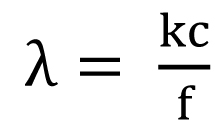


 , k = 0.6, c = 3.0•109 m/sec, and f = 106 Hz.


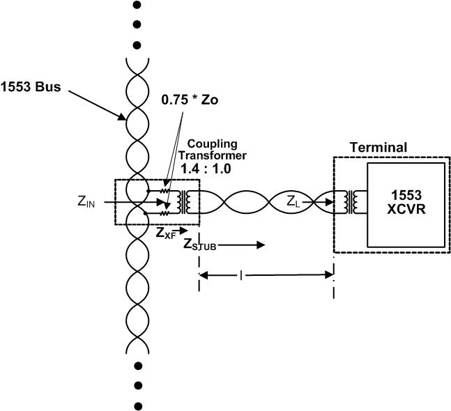 The equation for this impedance is:
 ; whereZ0 = cable characteristic impedance, which must be 70 to 85 ohms (nominally 78Ω)ZXF = coupling transformer input impedance at 1 MHz, looking from the main bus towards the stub. ZXF must ≥ 3,000 ohms.
 , where
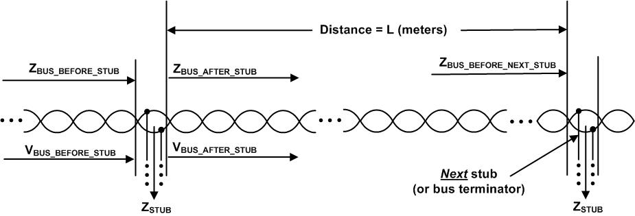 ZBUS_AFTER_STUB in Figure 3 is a function of the cable impedance, the distance to the next stub, and the bus impedance just before the next stub, ZBUS_BEFORE_NEXT_STUB. ZBUS_AFTER_STUB is computed as follows:
 These calculations repeat back until the transmitting BC or RT terminal. Referring to Figure 4, the bus impedance presented to the transmitting BC or RT is:
 where VBUS-TX = the voltage transmitted by the BC or RT. This allows the bus voltage to be computed at any point along the bus. If the voltages presented to all stubs on the bus is between 1.4 and 20 volts peak-to-peak for all direct coupled stubs, and between 1.0 and 14 volts peak-to-peak for all transformer coupled stubs, then the design of the bus (stubs, couplers, terminals, etc.) is compliant to MIL-STD-1553B.
