MIL-STD-1553 uses a variety of accessories to connect 1553 buses to one another. These accessories include cables, couplers, terminators, and connectors.
Cables

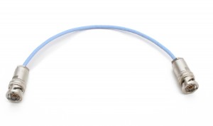
MIL-STD-1553 Cables, known as twinax cables, have a characteristic impedance on 78 ohms. The twinax cable is an electrical cable with two inner conductors surrounded by a flexible tubular insulating layer, surround by a tubular conduting shield.
There is no standardized length for these cables, but the maximum length of the bus is directly related to the gauge of the cable conductor and the time delay of the transmitted signal. These cables are commonly available in 36″, 72″, and 120″ with operating temperature ranges of -55°C to +200°C.
Examples of MIL-STD-1553 Cables
Couplers

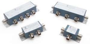
Bus Couplers provide electrical isolation on the MIL-STD-1553 data bus by employing coupling transformers and fault usolation resistors. Couplers contain two isolation resistors (one per wire) and an isolation transformer. The purpose of the bus coupler is to reduce reflections, maintain signal impedance levels, and protect the bus in an event of a short circuit.
Since direct coupled devices, without couplers, provide no DC isolation or common mode rejection, direct connection to the bus should be avoided. Therefore, without the bus couplers, any shorting fault between the device’s internal isolation resistors and the main bus will cause failure of the entire bus.
Bus couplers also have built-in fault isolation resistors, providing protection for the main bus in the event of a short circuit in the stub.
All devices, including the bus controller, bus monitor and remote terminal must be connected to the stub ends of the coupler. RFI dust caps (with or without safety chains) are recommended for all unused stub ports.
Bus Couplers are available from single stub to quad stub.
Examples of Bus Couplers
Terminators

MIL-STD-1553B states that both ends of the bus, whether it includes one coupler or a series of couplers connected together, must be terminated with 78 ohm terminators. At the two ends of the bus, resistors connect between the high and low signal wires either in internally terminated bus couplers or external connectorized terminators.
The purpose of electrical termination is to minimize the effects of signal reflections that can cause waveform distortion. If termination is not used, the communication signals can be comprimised, causing distruption or intermettent communication failures.
Examples of Terminators
Connectors

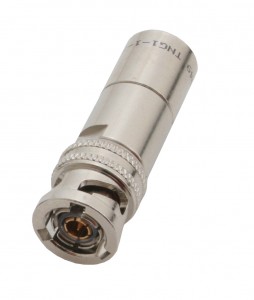
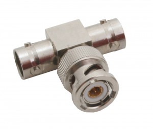
Connectors are used to connect bus cables and couplers to other cables and couplers. Since the MIL-STD-1553 does not specify the type of connector to use in data bus abpplications, the connectors must be compatible with the cable required by the specification. The most common connector type is the concentric twinax connector, which has three bayonet coupling slots/lugs.
The concentric twinax connector has a center pin and a cylindrical intermediate contact. The connector is available in standard (BNC size), miniature, and subminiature sizes. They are also offered in various solder/clamp and crimp assembly versions. Special pin and socket, keying and polarization are also available.